Method for manufacturing color filter substrate

a color filter film and substrate technology, applied in the field of display technology, can solve the problems of high cost of applying existing photolithographic techniques to the manufacture of quantum dots color filter films, inability to cover the entire color gamut, and inability to display colors. to achieve the effect of improving flatness

Inactive Publication Date: 2017-09-14
TCL CHINA STAR OPTOELECTRONICS TECH CO LTD
View PDF6 Cites 8 Cited by
  • Summary
  • Abstract
  • Description
  • Claims
  • Application Information

AI Technical Summary

Benefits of technology

The present invention provides a method for manufacturing a color filter substrate that overcomes the issue of color mixture and light leakage caused by the conventional method. By forming photoresist barrier walls on a black matrix before quantum dot pastes are dropped into sub-pixel zones, the method effectively prevents color mixture and maintains better flatness of the resulting color filter substrate. The method is easy to operate and the substrate manufactured therewith has better quality.

Problems solved by technology

Thin-film transistor liquid crystal displays (TFT-LCDs) take an important position among the display devices, due to quality of image displaying, low power consumption, and environmental friendliness, but the color displayed cannot cover the complete range of color gamut.
However, the quantum dots have a high price and the cost of applying the existing photolithographic techniques to the manufacture of quantum dot color filter film is extremely high because the utilization of the quantum dots is low and quantum dots losing the capability of light conversion resulting from being easily damaged by photo initiators.

Method used


Image

  • Method for manufacturing color filter substrate
  • Method for manufacturing color filter substrate
  • Method for manufacturing color filter substrate

Examples


Embodiment Construction

[0051]To further expound the technical solution adopted in the present invention and the advantages thereof, a detailed description is given to a preferred embodiment of the present invention and the attached drawings.

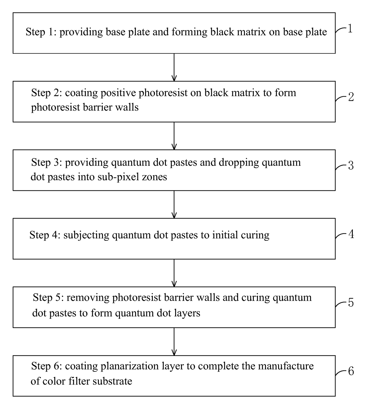
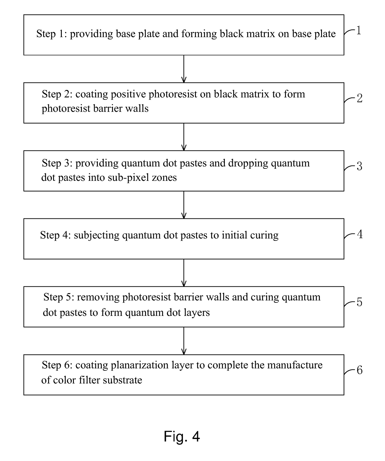
[0052]Referring to FIG. 4, the present invention provides a method for manufacturing a color filter substrate, which comprises the following steps:

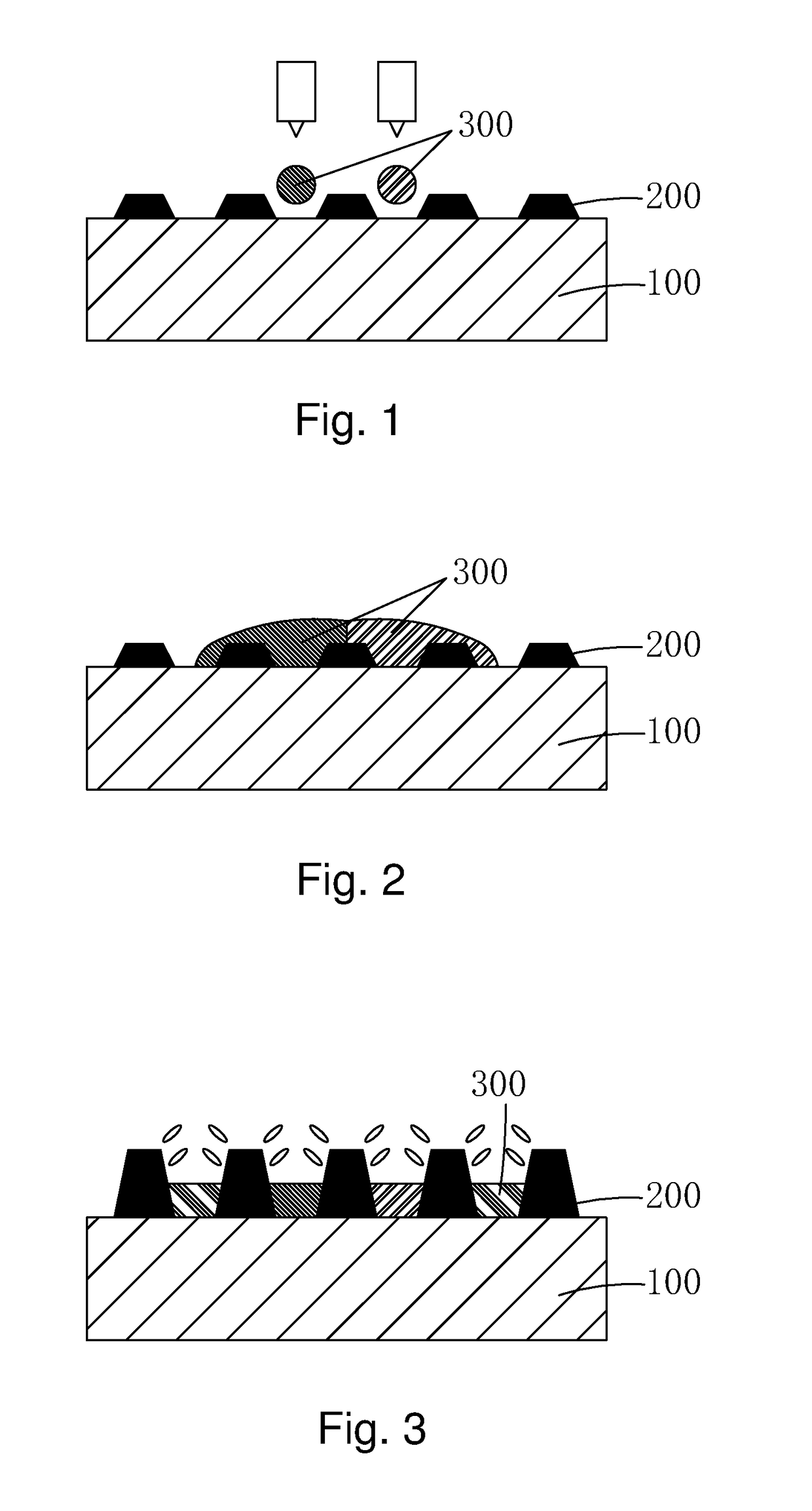
[0053]Step 1: as shown in FIG. 5, providing a base plate 1 and forming a black matrix 2 on the base plate 1 such that the black matrix 2 defines and circumferentially surrounds a plurality of sub-pixel zones 10 on the base plate 1.

[0054]Specifically, the base plate 1 comprises a transparent plate, preferably a glass plate.

[0055]Specifically, the plurality of sub-pixel zones 10 comprises a plurality of red sub-pixel zones 11, a plurality of green sub-pixel zones 12, and a plurality of blue sub-pixel zones 13.

[0056]Step 2: as shown in FIG. 6, coating positive photoresist on the black matrix 2 and the base plate 1 and subjectin...


PUM

PropertyMeasurementUnit
temperatureaaaaaaaaaa
particle sizeaaaaaaaaaa
transparentaaaaaaaaaa

Abstract

The present invention provides a method for manufacturing a color filter substrate. In the method for manufacturing a color filter substrate of the present invention, before quantum dot pastes are dropped into sub-pixel zones, photoresist barrier walls are first formed on a black matrix by means of positive photoresist to provide an effect of barrier in dropping the quantum dot paste. After the effect of barrier has been completed, the photoresist barrier walls are removed to prevent the problems of the convention color filter substrate manufacturing method that color mixture may result due to free flowing of quantum dot pastes caused by an excessively small height of the barrier walls and light leakage may result due to disorderly arrangement of liquid crystal caused by an excessively large height of barrier walls. The operation is easy and the color filter substrate so manufactured exhibits better flatness.

Description

BACKGROUND OF THE INVENTION[0001]1. Field of the Invention[0002]The present invention relates to the field of display technology, and in particular to a method for manufacturing a color filter substrate.[0003]2. The Related Arts[0004]Recently, with the progress of science and technology, the techniques of liquid crystal display have been continuously improved. Thin-film transistor liquid crystal displays (TFT-LCDs) take an important position among the display devices, due to quality of image displaying, low power consumption, and environmental friendliness, but the color displayed cannot cover the complete range of color gamut. Organic light-emitting diode (OLED) based display techniques that have emerged recently but are getting mature also have simple structures, reduced thickness, fast response, and capable of displaying richer colors. Further, with the advent of quantum dots, quantum dot displays have also been emerging. Since quantum dots have very narrow wavelength ranges of e...

Claims


Application Information

Patent Timeline
Patent Type & Authority Applications(United States)
IPC IPC(8): G03F7/00G02F1/1335B41J3/407
CPCG03F7/0007B41J3/407G02F1/133516G02F1/133512G02F2001/133302G02F2001/133614G02F2202/36G02F2001/133357G02F1/133621G02F1/133617G02F1/133357G02F1/133519G02F1/133302G02F1/133614
Inventor TANG, MIN
Owner TCL CHINA STAR OPTOELECTRONICS TECH CO LTD
Why Eureka
Try Eureka