
Control device for vehicle

Active Publication Date: 2017-09-14
SUBARU CORP
View PDF0 Cites 8 Cited by
  • Summary
  • Abstract
  • Description
  • Claims
  • Application Information

AI Technical Summary

Benefits of technology

The patent describes a way to improve the fuel efficiency of a vehicle by protecting its transmission. This is done by using a friction clutch that is placed between the engine and the transmission. The control device can decrease the force of the clutch when the pressure of the oil pump is low during deceleration. This results in better fuel efficiency for the vehicle.

Problems solved by technology

However, the engine stop before stopping the vehicle causes the oil pump to be stopped during the actuation of the continuously variable transmission, and causes a reduction in the control hydraulic pressure to slip the chain or the like.

Method used


Image

  • Control device for vehicle
  • Control device for vehicle
  • Control device for vehicle

Examples


Embodiment Construction

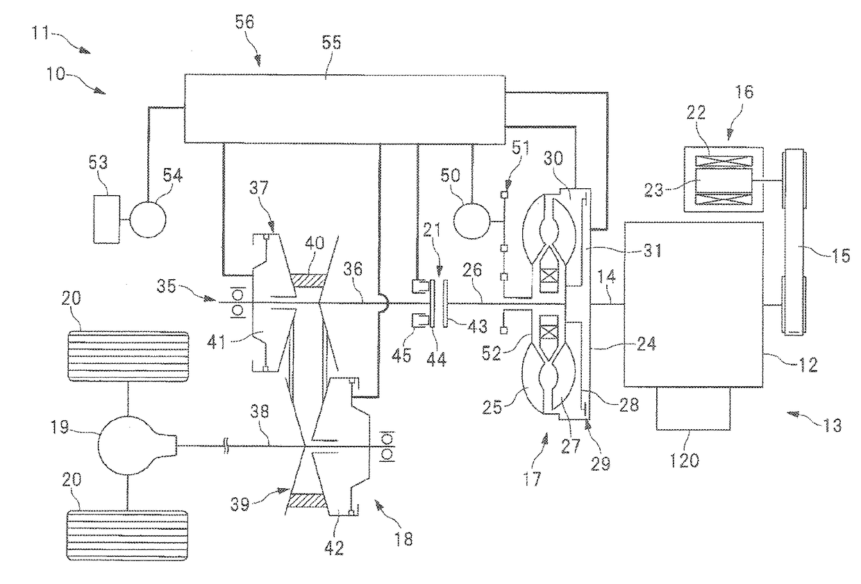
[0025]Hereinafter, an implementation of the present invention will be described with reference to the accompanying drawings in detail. FIG. 1 is a schematic diagram illustrating a configuration example of a vehicle 11 equipped with a vehicle control device 10 according to an implementation of the present invention. As illustrated in FIG. 1, a power unit 13 having an engine 12 is mounted on a vehicle 11. A starter generator 16 is coupled to a crank shaft 14 of the engine 12 through a belt mechanism 15. The engine 12 is also coupled to a continuously variable transmission 18 through a torque converter 17, and the continuously variable transmission 18 is coupled to wheels 20 through a differential mechanism 19 and so on. Further, a forward clutch 21 is disposed between the torque converter 17 and the continuously variable transmission 18.

[Starter Generator]

[0026]The starter generator 16 (electric motor, motor generator) 16 coupled to the engine 12 is a so-called ISG (integrated starter...


PUM


Abstract

Provided is a control device for a vehicle including a continuously variable transmission. The control device includes a lock-up clutch, an oil pump, an electric motor, and a device control unit. The lock-up clutch is disposed in a torque converter coupled to the engine and switchable between an engaged state and a released state. The oil pump is driven by the engine and supplies a hydraulic oil to the continuously variable transmission. The electric motor is coupled to the engine and controlled to be in a powering state in which the engine is rotationally driven. The device control unit controls the lock-up clutch to put into the released state and controls the electric motor to put into the powering state if a discharge pressure of the oil pump falls below a threshold value at the time of a vehicle deceleration in which a fuel supply to the engine is cut off.

Description

CROSS-REFERENCE TO RELATED APPLICATIONS[0001]The present application claims priority from Japanese Patent Application No. 2016-048878 filed on Mar. 11, 2016, the entire contents of which are hereby incorporated by reference.BACKGROUND[0002]1. Technical Field[0003]The present invention relates to a control device vehicle for a vehicle including a continuously variable transmission.[0004]2. Related Art[0005]As one of transmissions provided in a power transmission system for a vehicle, there is a continuously variable transmission in which a transmission gear ratio is continuously varied (refer to Japanese Unexamined Patent Application Publication (JP-A) No. 2010-78088 (Patent Literature 1), JP-A-2004-156774 (Patent Literature 2), JP-A-2013-24276 (Patent Literature 3)). In the continuously variable transmission of this type, a hydraulic oil is frequently supplied from an oil pump driven by an engine. In hydraulically controlling the continuously variable transmission, in order to preve...

Claims


Application Information

Patent Timeline
IPC IPC(8): B60W30/188B60W10/30F16H61/00B60W10/02
CPCB60W30/1886B60W10/026B60W10/02B60W10/30F16H61/0031B60W2710/1083B60W2510/108B60W2520/105B60W2520/04B60W2710/021B60W2710/024B60W2510/0623F16H61/143F16H61/66B60W10/08B60W30/18072B60W2510/1075B60W2520/10F16H61/662
Inventor OKADA, YUTAKINOSHITA, TAKAHIROHIRAO, KOICHI
Owner SUBARU CORP
Learn More