
Steerable introducer assembly for first percutaneously identifying target tissue and then defining a percutaneous path to the target tissue for an implantable medical device

a technology of implantable medical devices and introducers, which is applied in the direction of spinal electrodes, trocars, internal electrodes, etc., can solve the problems of increasing the likelihood of current flow, documenting does not, and electrode arrays with many individual electrodes

Active Publication Date: 2017-09-07
STRYKER CORP
View PDF0 Cites 179 Cited by
  • Summary
  • Abstract
  • Description
  • Claims
  • Application Information

AI Technical Summary

Benefits of technology

The insertion assembly described in this patent allows for the identification and positioning of target tissue before inserting an electrode array. The handpiece is designed to guide the electrode array to the target tissue and to retract the sheath and core to ensure proper placement. The technical effects of this invention include improved accuracy and efficiency in identifying and targeting tissue for treatment.

Problems solved by technology

In contrast to an electrode array with a smaller number of electrodes, use of the above-described array increases the likelihood that the current flow can be set to provide desired therapeutic effects, with tolerable side effects.
Previously, there was a disadvantage of providing an electrode array with numerous individual electrodes that collectively occupy a large surface area.
However, this document does not teach: how the folded over array is initially percutaneously inserted in the patient; how the array is initially positioned in the proper orientation for advancement to the target location; or the structure of tool that can be used to both advance the sheath-encased array to the target location while steering the array.
Also, the prior application does not disclose tools that can be used to first retract the sheath away from the array and then retract the core from out from underneath the folded over array.

Method used


Image

  • Steerable introducer assembly for first percutaneously identifying target tissue and then defining a percutaneous path to the target tissue for an implantable medical device
  • Steerable introducer assembly for first percutaneously identifying target tissue and then defining a percutaneous path to the target tissue for an implantable medical device
  • Steerable introducer assembly for first percutaneously identifying target tissue and then defining a percutaneous path to the target tissue for an implantable medical device

Examples


Embodiment Construction

I. Overview

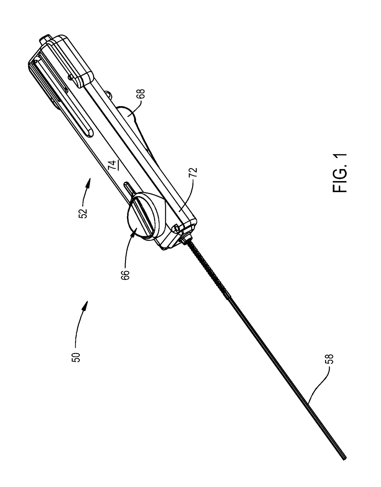
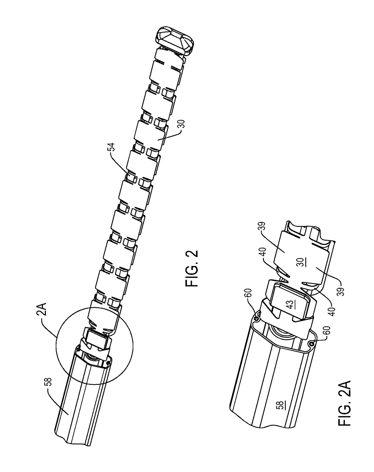
[0082]FIGS. 1 and 2 illustrate components of system 50 of this invention used to percutaneously, insert, steer and deploy an implantable medical device. This type of device provides a therapeutic benefit and / or diagnostic information.

[0083]The representative implantable medical device is an electrode array 30. System 50 includes a handpiece 52. Located distally forward of the handpiece 50 is a core 54. (Here “distal” means away from the practitioner holding the handpiece / towards the target location. “Proximal” means towards the practitioner / away from the target location.) The electrode array 30 is folded, or rolled, over the distal portion of the core 54. Proximal to where the electrode array 30 is folded\bent\wrapped over the core 54, wires forming the core are secured over the outer surface of a spring 56 (identified in FIG. 33). The wires forming core 54 and spring 56 extend proximally, into handpiece 52. Also extending forward from the handpiece 52 is a sheath 58. The...


PUM


Abstract

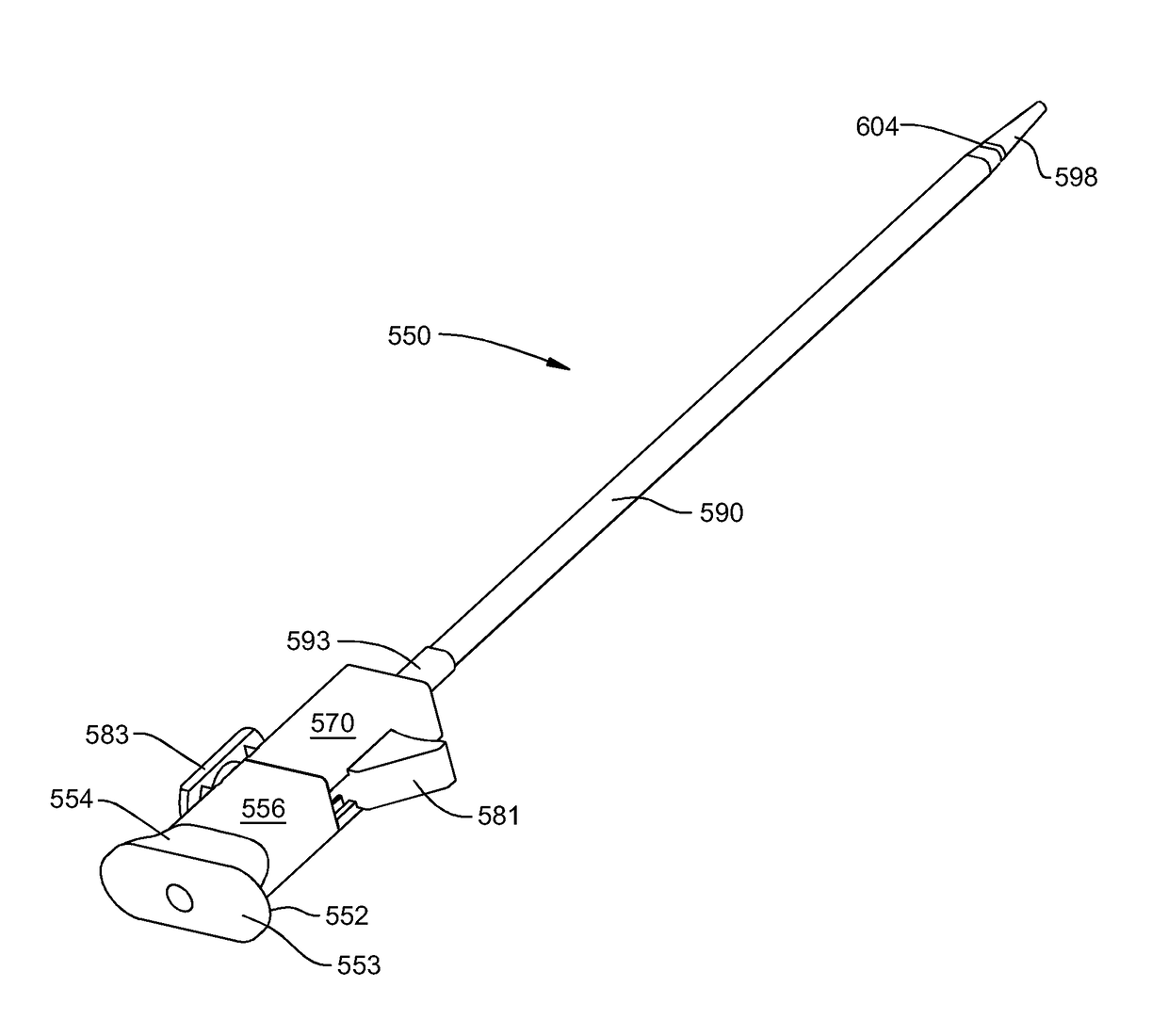
An assembly for both targeting a location in a living being at which an implantable medical device is to be inserted and defining a percutaneous path to the target location. The assembly includes a guidewire with electrodes that is inserted percutaneously into the living being. Electrodes on the guidewire source and sink current to facilitate the identification of the target location. A dilator encased in a reinforced sleeve is disposed over the guidewire. Steering wires in the sleeve facilitate the advancement of the sleeve and the guidewire. Once the dilator and sleeve are advanced to the target location, the dilator is removed from the sleeve. The lumen in sleeve functions as the lumen in the living being through which the implantable device is delivered to the target location.

Description

RELATIONSHIP TO PRIORITY APPLICATIONS[0001]This application is a continuation of U.S. patent application Ser. No. 14 / 089,015 filed 25 Nov. 2013, now U.S. Pat. No. 9,655,645. Application Ser. No. 14 / 089,015 is a continuation of PCT Pat. App. No. PCT / US2012 / 039130 filed 23 May 2012. PCT Pat. App. No. PCT / US2012 / 039130 is a non-provisional of U.S. Prov. Pat. App. No 61 / 490,876 filed 27 May 2011. The priority applications are specifically incorporated herein by reference.FIELD OF THE INVENTION[0002]This invention relates generally to a system and method for percutaneously inserting and deploying an implantable medical device array. More particularly, the system of this invention is able to insert the device in a minimally invasive procedure, steer the device to a target location and then, if appropriate unfold the device.BACKGROUND OF THE INVENTION[0003]There are a number of medical conditions for which it has been found that an effective therapy involves driving current through a secti...

Claims


Application Information

Patent Timeline
Patent Type & Authority Applications(United States)
IPC IPC(8): A61B17/34A61N1/05
CPCA61B17/3468A61N1/0558
Inventor STAUNTON, DOUGLAS A.
Owner STRYKER CORP
Learn More