
Manufacturing display panels with integrated micro lens array

a technology of display panels and micro-lens arrays, applied in the field of display panels integrated with micro-lens arrays, can solve the problems of wasting most of the light emitted at a large viewing angle, and achieve the effects of reducing power waste, reducing light divergence angle, and increasing brightness

Active Publication Date: 2017-08-24
JADE BIRD DISPLAY SHANG HAI LTD
View PDF2 Cites 27 Cited by
  • Summary
  • Abstract
  • Description
  • Claims
  • Application Information

AI Technical Summary

Benefits of technology

The patent describes a display panel that includes a micro lens array integrated with pixel light sources and driver circuits. The micro lenses are positioned to reduce the divergence of light produced by the pixel light sources, which improves image brightness and reduces power waste. The use of the micro lens array also enhances viewing angles and protects user privacy in public areas.

Problems solved by technology

In this case, compared with stationary large screens, light emitted at a large viewing angle is mostly wasted.
Additionally, large viewing angles raise privacy concerns for portable electronic devices used in public areas.

Method used


Image

  • Manufacturing display panels with integrated micro lens array
  • Manufacturing display panels with integrated micro lens array
  • Manufacturing display panels with integrated micro lens array

Examples


Embodiment Construction

[0022]The figures and the following description relate to preferred embodiments by way of illustration only. It should be noted that from the following discussion, alternative embodiments of the structures and methods disclosed herein will be readily recognized as viable alternatives that may be employed without departing from the principles of what is claimed.

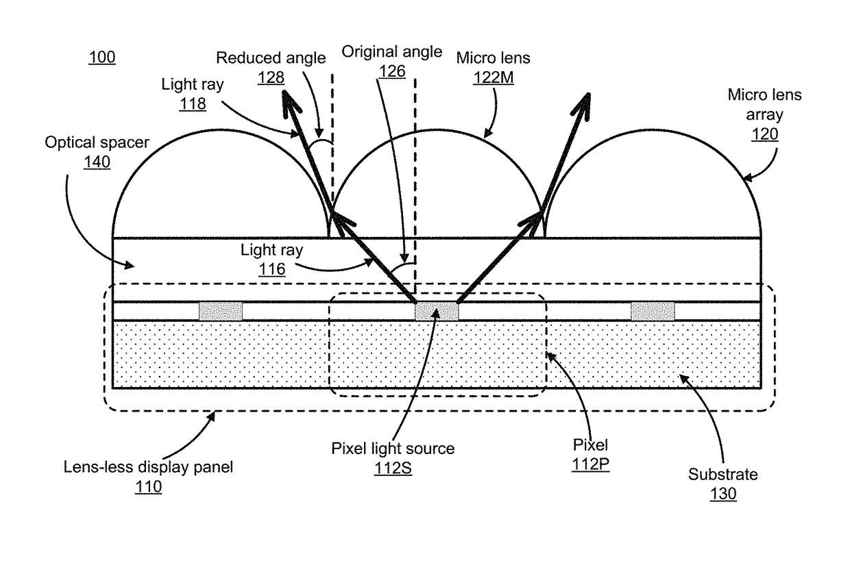
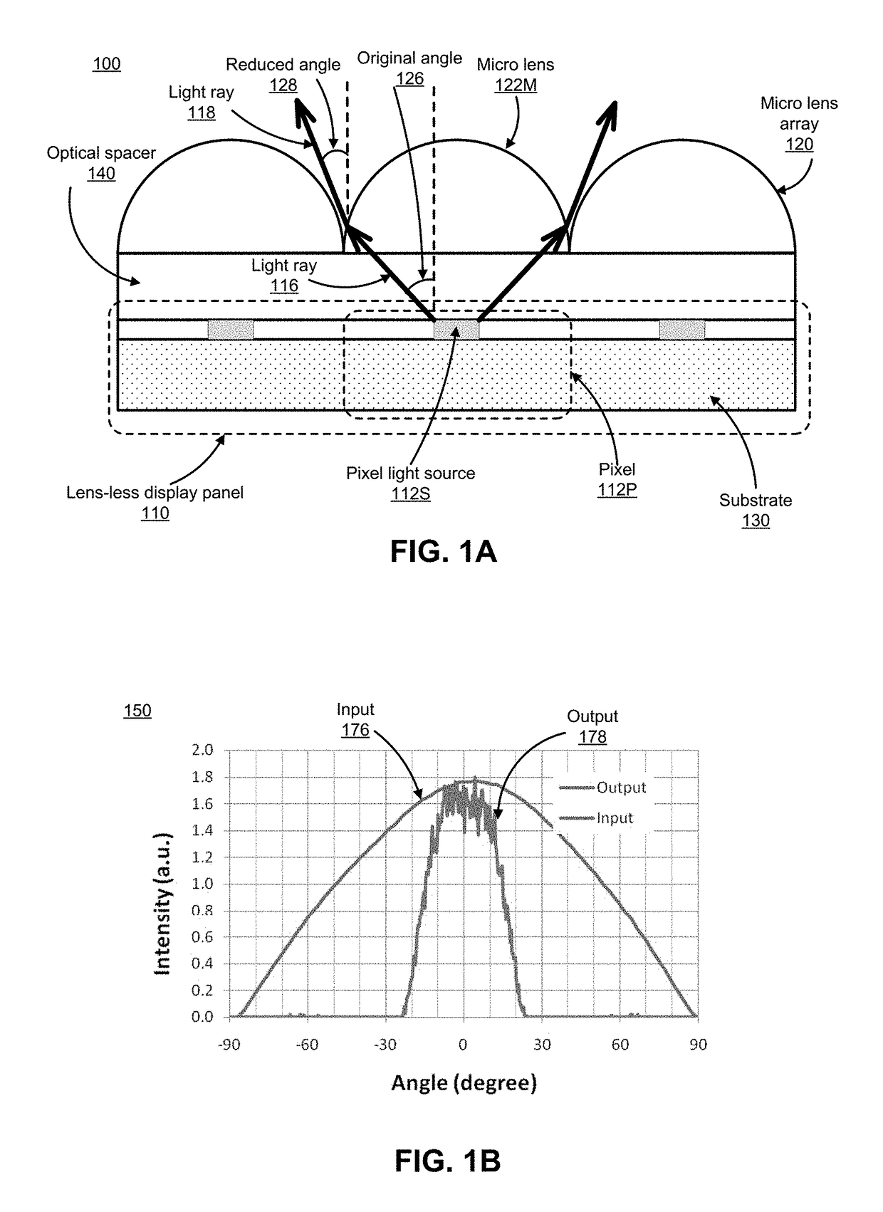
[0023]FIG. 1A is a cross-sectional view of an example display panel 100 integrated with a micro lens array 120, according to one embodiment. In FIG. 1A, the finished display panel 100 includes a lens-less display panel 110 (i.e., without a micro lens array), a micro lens array 120, and an optical spacer 140 formed between the lens-less display panel and the micro lens array. The display panel 100 typically includes an array of individual pixels 112P, each of which further includes a pixel driver circuit (not shown in FIG. 1A) and a corresponding pixel light source 112S that is electrically coupled to and driven by the pixel dr...


PUM


Abstract

Various embodiments include a display panel with integrated micro lens array. The display panel typically includes an array of pixel light sources (e.g., LEDs) electrically coupled to corresponding pixel driver circuits (e.g., FETs). The array of micro lenses are aligned to the pixel light sources and positioned to reduce the divergence of light produced by the pixel light sources. The display panel may also include an integrated optical spacer to maintain the positioning between the micro lenses and pixel driver circuits.

Description

CROSS-REFERENCE TO RELATED APPLICATION(S)[0001]This application is a continuation of U.S. patent application Ser. No. 15 / 269,956, “Display panels with integrated micro lens array,” filed Sep. 19, 2016; which claims priority under 35 U.S.C. §119(e) to U.S. Provisional Patent Application Ser. No. 62 / 299,511, “Display panels with integrated micro lens array,” filed Feb. 24, 2016 and to U.S. Provisional Patent Application Ser. No. 62 / 302,963, “Display panels with integrated micro lens array,” filed March 3, 2016. The subject matter of all of the foregoing is incorporated herein by reference in their entirety.BACKGROUND[0002]1. Field of the Invention[0003]This disclosure relates generally to display panels integrated with a micro lens array.[0004]2. Description of Related Art[0005]Display technologies are becoming increasingly popular in today's commercial electronic devices. These display panels are widely used in stationary large screens such as liquid crystal display televisions (LCD ...

Claims


Application Information

Patent Timeline
Patent Type & Authority Applications(United States)
IPC IPC(8): G02B3/00
CPCG02B3/0012G02B3/0018G02B3/0037G09G3/346G02B3/0031G02B3/0056G02B3/0075G09G2320/0233H01L25/0753H01L25/00G09G3/2092G09G3/3406G09G2320/028G09G2330/021
Inventor ZHANG, LEIOU, FANGLI, QIMING
Owner JADE BIRD DISPLAY SHANG HAI LTD
Learn More