Method of detecting failure or anomaly of sensor terminal
- Summary
- Abstract
- Description
- Claims
- Application Information
AI Technical Summary
Benefits of technology
Problems solved by technology
Method used
Image
Examples
first embodiment
[0029]In this embodiment, fundamental examples of an apparatus configuration and a processing flow for realizing a detection method according to the present invention will be shown.
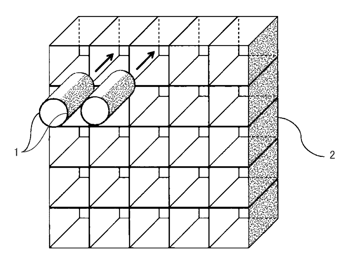
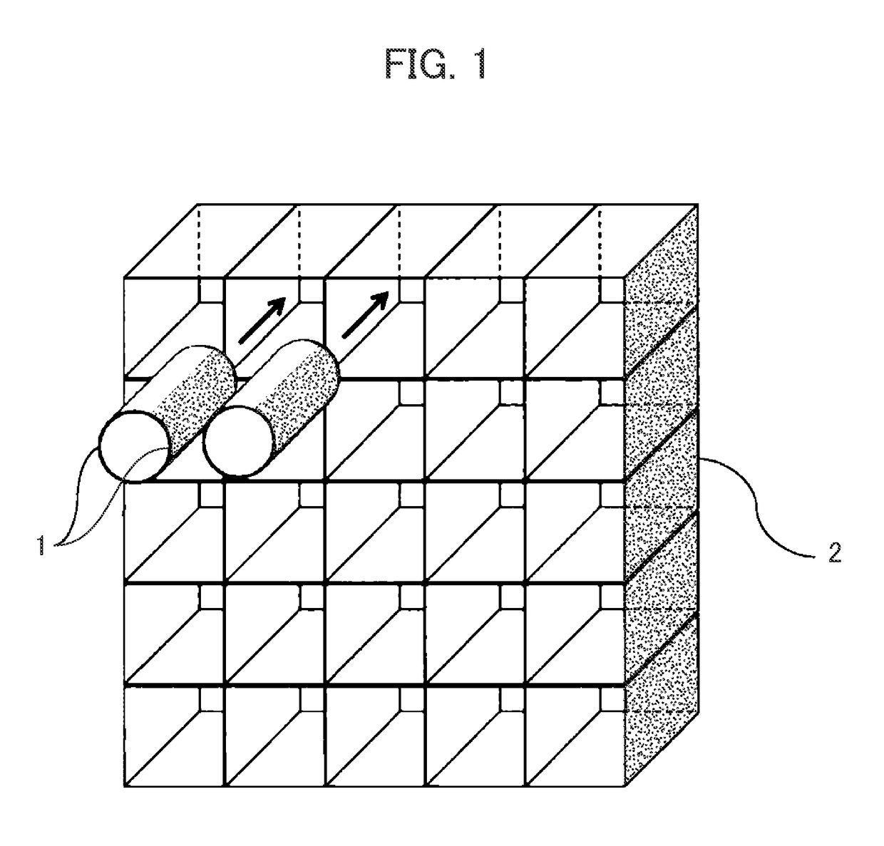
[0030]FIG. 1 is the schematic diagram of an apparatus configuration that can be used for a detection method according to the present invention. A housing device 2 includes slots of the shape of a grid lattice for housing plural sensor terminals 1. Each slot has means for detecting whether a sensor terminal 1 is housed in itself or not, and the housing device 2 can always grasp in which slots sensor terminals 1 are housed. The means for detecting whether a sensor terminal 1 is housed in a slot or not can be realized with the use of, for example, a mechanical switch, an RFID, local wireless communication means, an infrared sensor, an image sensor. When the housing device 2 detects that a sensor terminal 1 is housed in a certain slot, the housing device 2 establishes communication connection with the sensor ...
second embodiment
[0045]In this embodiment, another example of an apparatus configuration and another example of a processing flow for realizing a detection method according to the present invention will be explained.
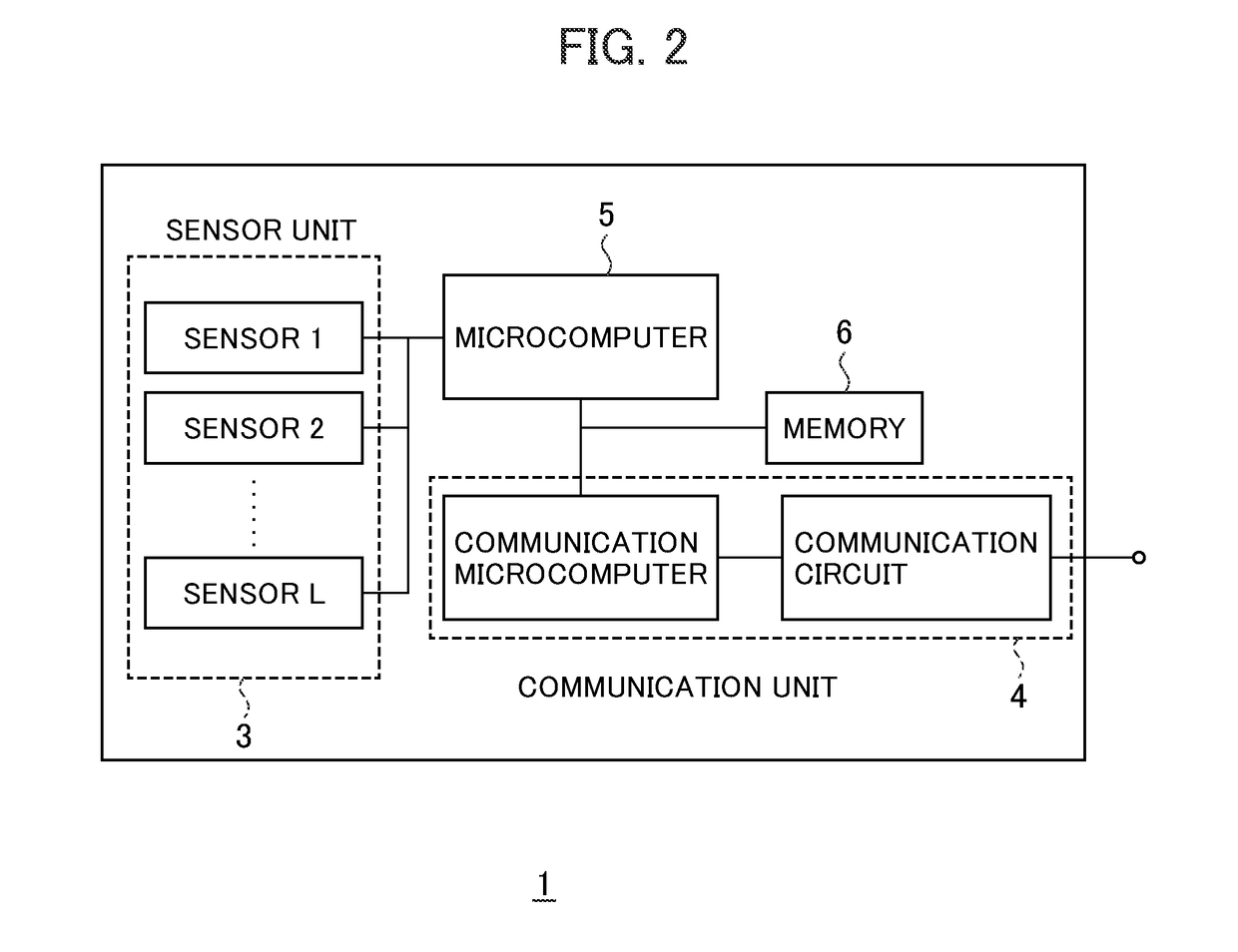
[0046]FIG. 7 is a block diagram of a sensor terminal 1. The sensor terminal 1 includes: a sensor unit 3 including a sensor 1 to a sensor L; a communication unit 4 including a communication microcomputer and a communication circuit; a microcomputer 5; a memory 6; and a charging unit 7 including a battery and a charging circuit 7. The sensor 1 to the sensor L that are included in the sensor unit 3 are, for example, acceleration sensors; velocity sensors; GNSS vibration reception devices; temperature sensors; illumination sensors; humidity sensors; or pressure sensors, and the sensor 1 to the sensor L include at least one sensor. It is preferred that the communication unit 4 should perform wireless communication, and should be capable of utilizing, for example, a wireless LAN compliant with...
third embodiment
[0054]In this embodiment, an example of a comparison operation that can be used for a detection method according to the present invention is shown.
[0055]FIG. 10 shows an example of a vibration reception signal output by a sensor terminal. In this case, the vibration reception signal is time-series acceleration data. Although the sampling time-interval for the time-series acceleration data is within several microseconds and several milliseconds, any other value can be adopted as the sampling time-interval in accordance with the request level of the accuracy of analysis. In seismic exploration, data output by a one-dimensional acceleration sensor, the direction of which is vertical to the ground surface, is generally used. However, in more advanced seismic exploration, it is conceivable that data obtained by a three-axis acceleration sensor and other auxiliary sensors is used.
[0056]FIG. 11 is a block diagram of a first example of the comparison operation. A comparison calculation is e...
PUM
 Abstract
Description
Claims
Application Information
 - R&D
- Intellectual Property
- Life Sciences
- Materials
- Tech Scout
- Unparalleled Data Quality
- Higher Quality Content
- 60% Fewer Hallucinations
Browse by: Latest US Patents, China's latest patents, Technical Efficacy Thesaurus, Application Domain, Technology Topic, Popular Technical Reports.
© 2025 PatSnap. All rights reserved.Legal|Privacy policy|Modern Slavery Act Transparency Statement|Sitemap|About US| Contact US: help@patsnap.com


