
Premagnetizing of mmc connected transformer

a transformer and preamplifying technology, applied in the field of modular multi-level converters, can solve the problems of transformer inrush, detrimental to the switch, saturation of the transformer core and corresponding inductance drop, etc., to reduce engineering effort and material cost, reduce short-circuit impedance ratio, and minimize inrush current

Active Publication Date: 2017-08-03
HITACHI ENERGY SWITZERLAND AG
View PDF2 Cites 4 Cited by
  • Summary
  • Abstract
  • Description
  • Claims
  • Application Information

AI Technical Summary

Benefits of technology

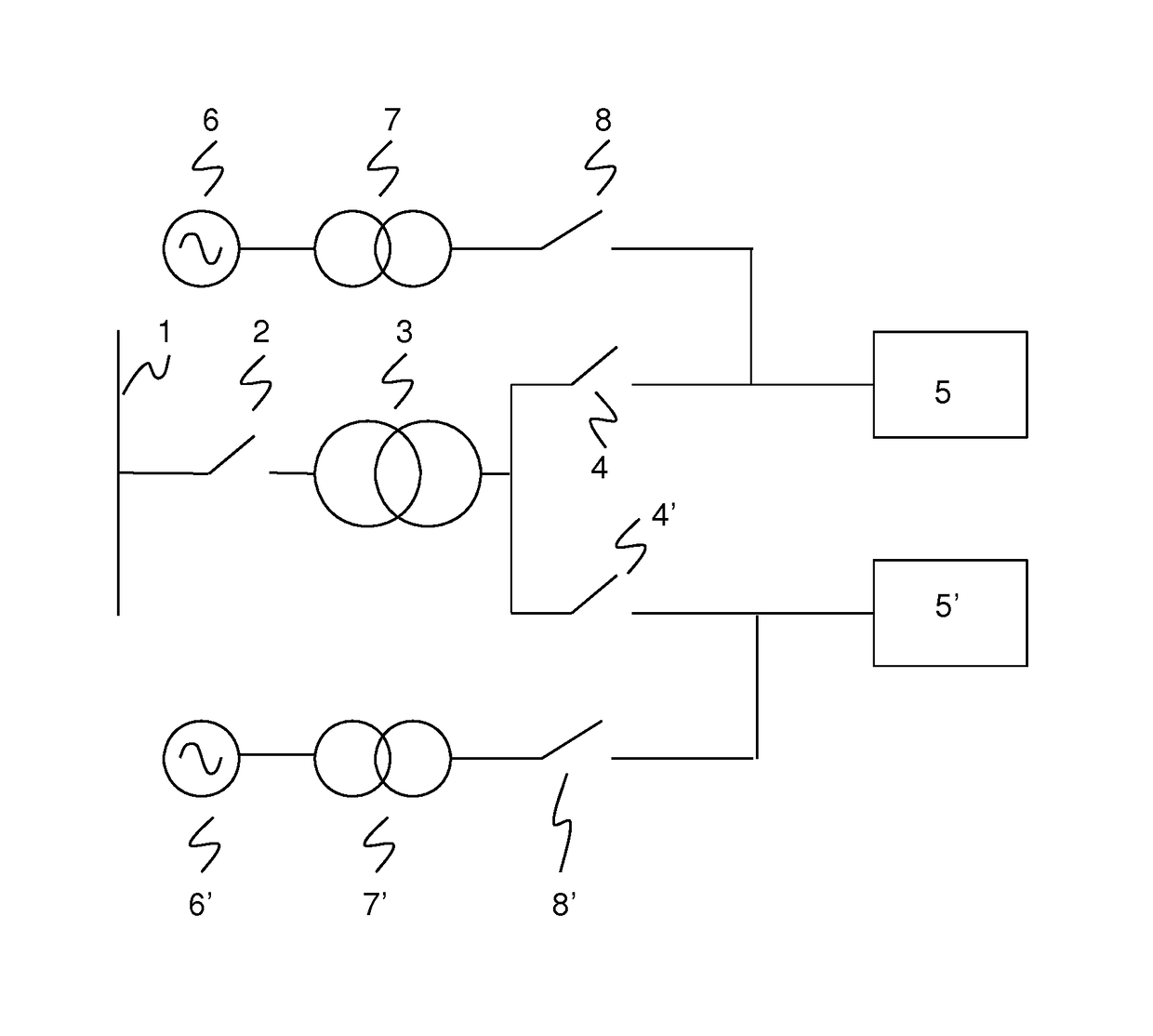
This patent describes a method for controlling the magnetization of a transformer to minimize inrush current without needing a DC intermediate circuit. The method uses a low-power and low-cost AC supply to charge the converter, which then uses its wide bandwidth to quickly magnetize the transformer without voltage ramping. This approach reduces the engineering and material costs of the system, especially for high-voltage, high-current, or low-short-circuit impedance ratios. The method also allows the converter to manage the magnetization of the transformer while not depleting the converter's capacitors. This approach is useful for a wide range of power system configurations.

Problems solved by technology

Transformer inrush is an undesired or often unacceptable effect of directly connecting a transformer to an electric grid.
Uncontrolled, and specifically unlimited, transformer inrush currents may lead to saturation of the transformer core and corresponding inductance drop.
According to the patent application EP 1024574 A2 a transformer connected to an AC network via a power switch in an unsynchronized manner causes both inrush currents that are detrimental to the switch, as well as residual DC currents through unbalanced transformer core saturation that are inacceptable for traction applications.
The appropriately sized auxiliary transformer with a power rating sufficient to pre-magnetize the power transformer as well as to charge the converter incurs additional cost.

Method used


Image

  • Premagnetizing of mmc connected transformer
  • Premagnetizing of mmc connected transformer
  • Premagnetizing of mmc connected transformer

Examples


Embodiment Construction

[0009]It is therefore an objective of the invention to simplify pre-magnetizing of a modular multilevel converter connected transformer in order to moderate inrush currents upon connecting the transformer to an electric grid. This objective is achieved by a method and a controller according to the independent claims. Preferred embodiments are evident from the dependent patent claims.

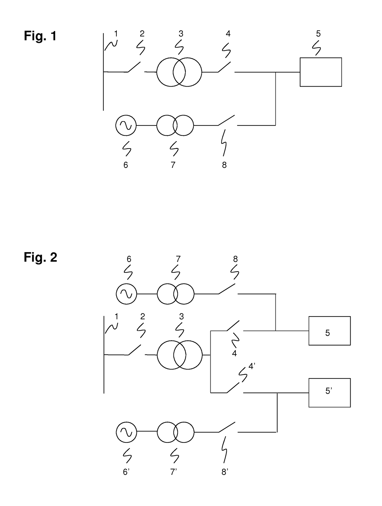
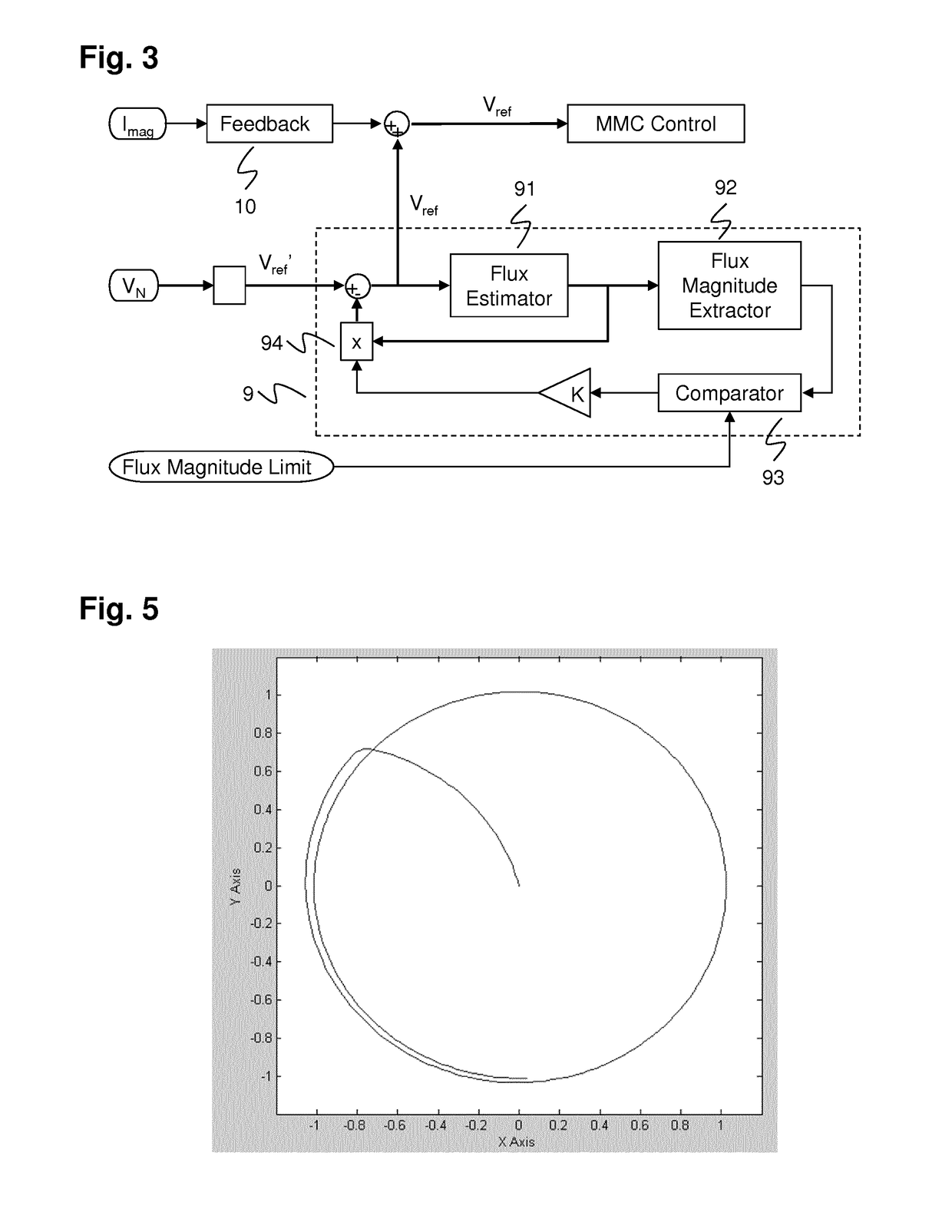
[0010]The invention makes use of the unique characteristics of Modular Multilevel power Converters (MMC) and takes advantage of the high amount of stored energy in MMC converters as compared to other converter types. This stored energy is used to pre-magnetize a converter-connected main transformer, therefore no additional or dedicated pre-magnetizing hardware is required in addition to the charging hardware provided to charge the converter capacitors. As the transformer pre-magnetizing takes place subsequent to the converter charging, the converter charging circuit is not used to, and therefore does not...


PUM


Abstract

The present invention is concerned with pre-magnetizing a Modular Multilevel power Converters connected transformer in order to moderate inrush currents upon connecting the transformer to an electric grid. The invention takes advantage of the high amount of stored energy in MMC converters as compared to other converter types. This stored energy is used to pre-magnetize the converter-connected transformer, therefore no additional or dedicated pre-magnetizing hardware is required in addition to the charging hardware provided to charge the converter capacitors. As the transformer pre-magnetizing takes place subsequent to the converter charging, the converter charging circuit is not used to, and therefore does not need to be designed to, directly magnetize the transformer.

Description

FIELD OF THE INVENTION[0001]The invention relates to the field of modular multilevel converters, and specifically to pre-magnetizing of a converter connected transformer in order to moderate inrush currents upon connecting the transformer to an electric grid.BACKGROUND OF THE INVENTION[0002]A Modular Multilevel power Converter (MMC), also known as Chain-Link Converter (CLC), comprises a plurality of converter cells, or converter (sub-) modules, serially connected in converter branches that in turn may be arranged in a wye / star, delta, and / or indirect converter topology. Each converter cell comprises, in the form of a half-bridge or full-bridge circuit, a capacitor for storing energy and power semiconductor switches such as insulated gate bipolar transistor (IGBT) devices, gate-turn-off thyristor (GTO) devices, or MOSFETs for connecting the capacitor to the converter branch with one or two polarities. The voltage per converter cell capacitor may be between 1 kV and 3 kV; whereas the ...

Claims


Application Information

Patent Timeline
Patent Type & Authority Applications(United States)
IPC IPC(8): H02H9/00H02H9/04H02M7/48H02M5/22H02M1/42H02M7/12
CPCH02H9/002H02M1/42H02H9/045H02M7/48H02M5/22H02M7/12H02H7/0455H02M1/36H02M1/40H02M5/12H02M7/4835Y02E40/20
Inventor TURNER, ROBERT
Owner HITACHI ENERGY SWITZERLAND AG
Learn More