
Ultraviolet-Based Gas Sensor

a gas sensor and ultraviolet light technology, applied in the field of ultraviolet light emitting diodes (uv led)based gas detection, can solve the problems of limited lamp operation life, increased ozone levels, and less effective calibration of these detectors

Active Publication Date: 2017-08-03
SENSOR ELECTRONICS TECH
View PDF2 Cites 13 Cited by
  • Summary
  • Abstract
  • Description
  • Claims
  • Application Information

AI Technical Summary

Benefits of technology

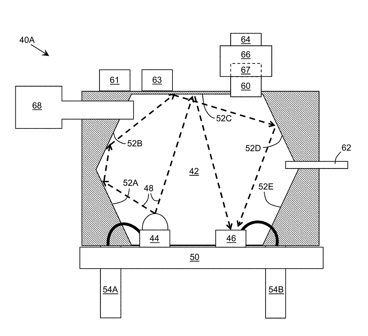
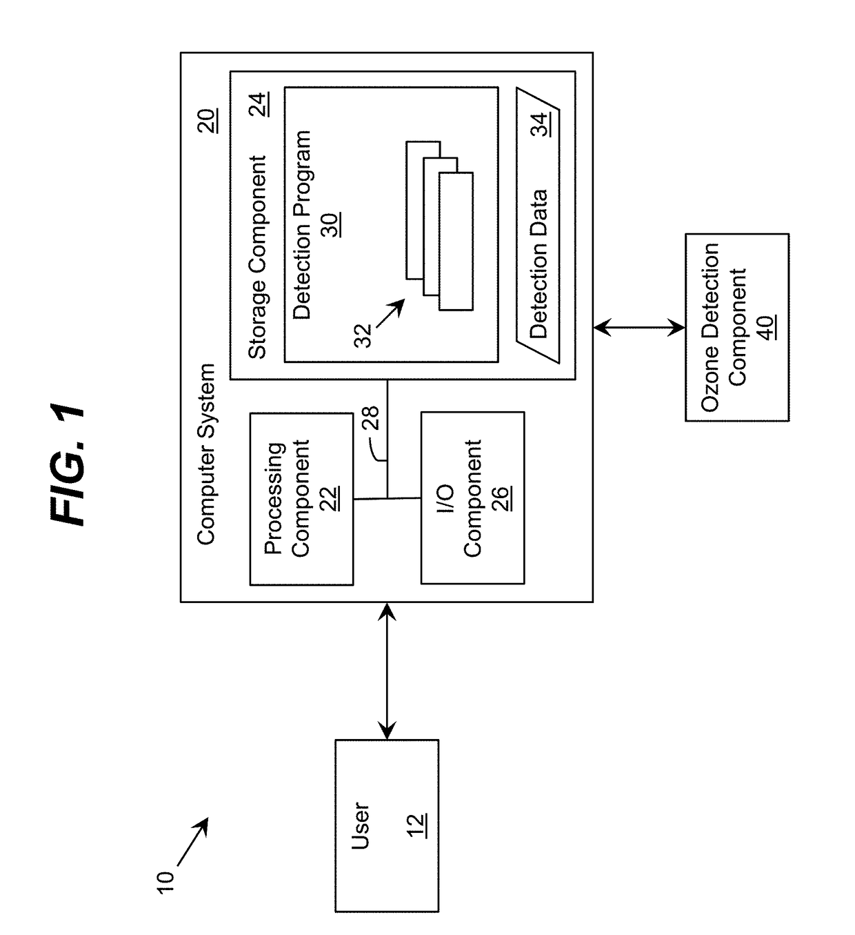
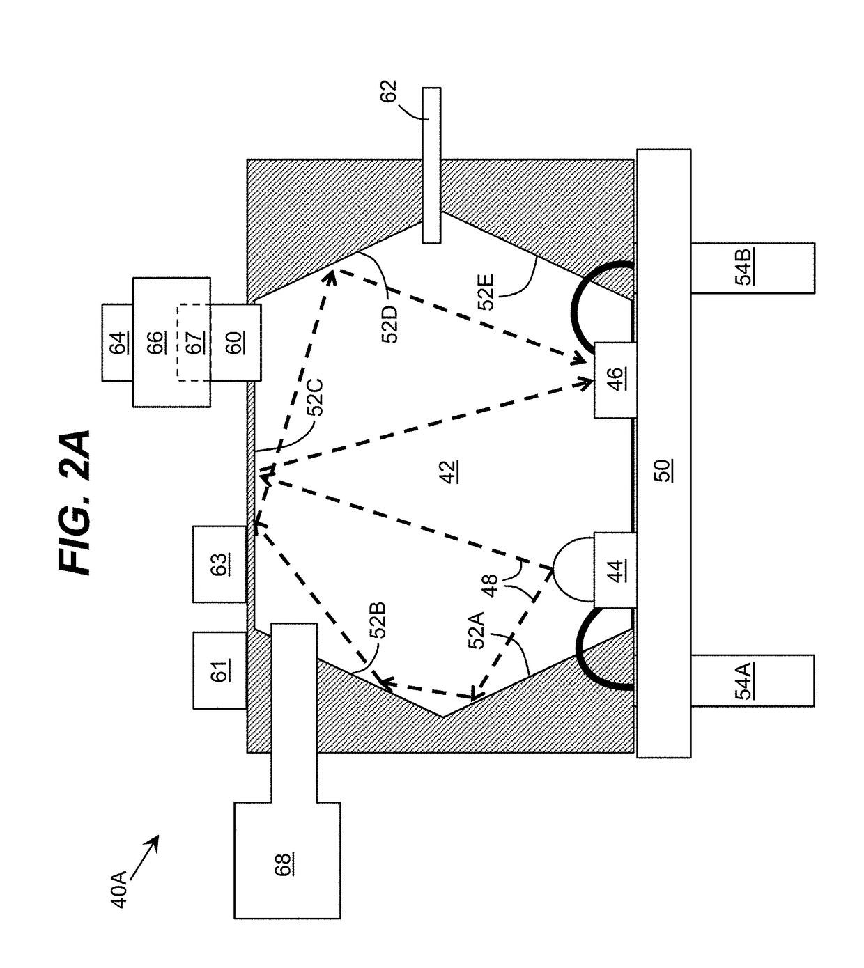
This invention is about a system and method for evaluating a gas sample for the presence of a trace gas, such as ozone. The system includes a chamber, an ultraviolet source mounted inside the chamber, and an ultraviolet detector mounted inside the chamber with reflecting walls and / or structures to guide ultraviolet light. A computer system operates the ultraviolet source in a high power pulse mode, and data is acquired corresponding to the intensity of the ultraviolet radiation detected by the ultraviolet detector while the sample gas is present in the chamber. The system can determine the presence and amount of the trace gas in the sample gas using this data. Another aspect of the invention provides a system with a pumping system for introducing gas into the chamber and removing ozone from the gas using a filter. The system operates the ultraviolet source after sealing the chamber and acquiring data corresponding to the intensity of ultraviolet radiation detected during the evaluation. The invention can be used in various applications, such as air quality monitoring, industrial process monitoring, and medical diagnostics.

Problems solved by technology

Excess levels of ozone can be dangerous to the health of humans.
Typically, these devices utilize mercury discharge lamps, which necessitate relatively large detectors with lamps having a limited operational lifetime.
Calibration of these detectors may be less effective as the devices age and / or interact with different environmental factors affecting an overall performance of the detector.
The detectors that utilize electrochemical effects often cannot accurately register small levels of ozone concentration present in the atmosphere, which, nevertheless, can be hazardous to human health.

Method used


Image

  • Ultraviolet-Based Gas Sensor
  • Ultraviolet-Based Gas Sensor
  • Ultraviolet-Based Gas Sensor

Examples


Embodiment Construction

[0024]As indicated above, aspects of the invention provide a solution for evaluating a sample gas for a presence of a trace gas, such as ozone. The solution uses an ultraviolet source and an ultraviolet detector mounted in a chamber. The chamber can include reflecting walls and / or structures configured to guide ultraviolet light. A computer system can operate the ultraviolet source in a high power pulse mode and acquire data corresponding to an intensity of the ultraviolet radiation detected by the ultraviolet detector while a sample gas is present in the chamber. Using the data, the computer system can determine a presence and / or an amount of the trace gas in the sample gas. The solution can provide a compact detector, which can overcome one or more shortcomings associated with previous mercury lamp-based solutions. As used herein, unless otherwise noted, the term “set” means one or more (i.e., at least one) and the phrase “any solution” means any now known or later developed solut...


PUM

PropertyMeasurementUnit
opening angleaaaaaaaaaa
peak wavelengthsaaaaaaaaaa
frequencyaaaaaaaaaa

Abstract

A solution for evaluating a sample gas for a presence of a trace gas, such as ozone, is provided. The solution uses an ultraviolet source and an ultraviolet detector mounted in a chamber. The chamber can include reflecting walls and / or structures configured to guide ultraviolet light. A computer system can operate the ultraviolet source in a high power pulse mode and acquire data corresponding to an intensity of the ultraviolet radiation detected by the ultraviolet detector while a sample gas is present in the chamber. Using the data, the computer system can determine a presence and / or an amount of the trace gas in the sample gas.

Description

REFERENCE TO RELATED APPLICATIONS[0001]The current application is a continuation-in-part of U.S. patent application Ser. No. 13 / 863,437, filed on 16 Apr. 2013, which claims the benefit of U.S. Provisional Application No. 61 / 624,716, filed on 16 Apr. 2012, each of which is hereby incorporated by reference.TECHNICAL FIELD[0002]The disclosure relates generally to gas detection, and more particularly, to ultraviolet light emitting diode (UV LED)-based gas detection.BACKGROUND ART[0003]Excess levels of ozone can be dangerous to the health of humans. As a result, there are strict regulations regarding human exposure to large doses of ozone. To warn the public of a high concentration of ozone in the atmosphere, ozone levels are monitored using ozone detectors. Current ozone detectors generally fall into three classes: detectors that operate based on ozone light absorption; detectors that operate based on semiconductor devices designed to sense ozone in air passed over the semiconductor dev...

Claims


Application Information

Patent Timeline
Patent Type & Authority Applications(United States)
IPC IPC(8): G01N21/03G01N21/59G01N21/33G01N21/11
CPCG01N21/031G01N21/11G01N2021/0106G01N21/33G01N2021/0378G01N21/59G01N21/05G01N21/274G01N2201/0696
Inventor BILENKO, YURIDOBRINSKY, ALEXANDERSHUR, MICHAELGASKA, REMIGIJUS
Owner SENSOR ELECTRONICS TECH
Learn More