Portable medical imaging system

a medical imaging and portable technology, applied in the field of medical imaging systems, can solve the problems of limited freedom of movement, hindering the acceptance and use of mobile three-dimensional imaging systems, and limited freedom of movement to effectively position the system without moving the patient, etc., and achieves the effect of extending the field of view

Active Publication Date: 2017-08-03
GLOBUS MEDICAL INC
View PDF40 Cites 176 Cited by
  • Summary
  • Abstract
  • Description
  • Claims
  • Application Information

AI Technical Summary

Benefits of technology

This patent describes a portable medical imaging system that can capture a larger field of view. It includes a movable C-arm with a detachable imaging signal transmitter and sensor. The system also has two translation devices that allow the imaging devices to move from the center axis of the system. This allows for a wider capture of the patient's area of interest. The technical effect is that this portable medical imaging system can capture larger and more complete images of patient's anatomy with a single positioning of the detachable imaging devices.

Problems solved by technology

While mobile solutions for ‘non-radiology department’ and patient-centric 3-D imaging do exist, they are often limited by their freedom of movement to effectively position the system without moving the patient.
Their limited freedom of movement has hindered the acceptance and use of mobile three-dimensional imaging systems.
One issue during imaging is the precise positioning of the imaging system.
This is especially important in an operating room or operating theatre, in which the size and weight of the imaging equipment and the presence of numerous required personnel make it difficult to precisely position the imaging equipment.

Method used


Image

  • Portable medical imaging system
  • Portable medical imaging system
  • Portable medical imaging system

Examples


Embodiment Construction

[0031]For purposes of this application, the terms “code”, “software”, “program”, “application”, “software code”, “software module”, “module” and “software program” are used interchangeably to mean software instructions that are executable by a processor. A “user” can be a physician, nurse, or other medical professional.

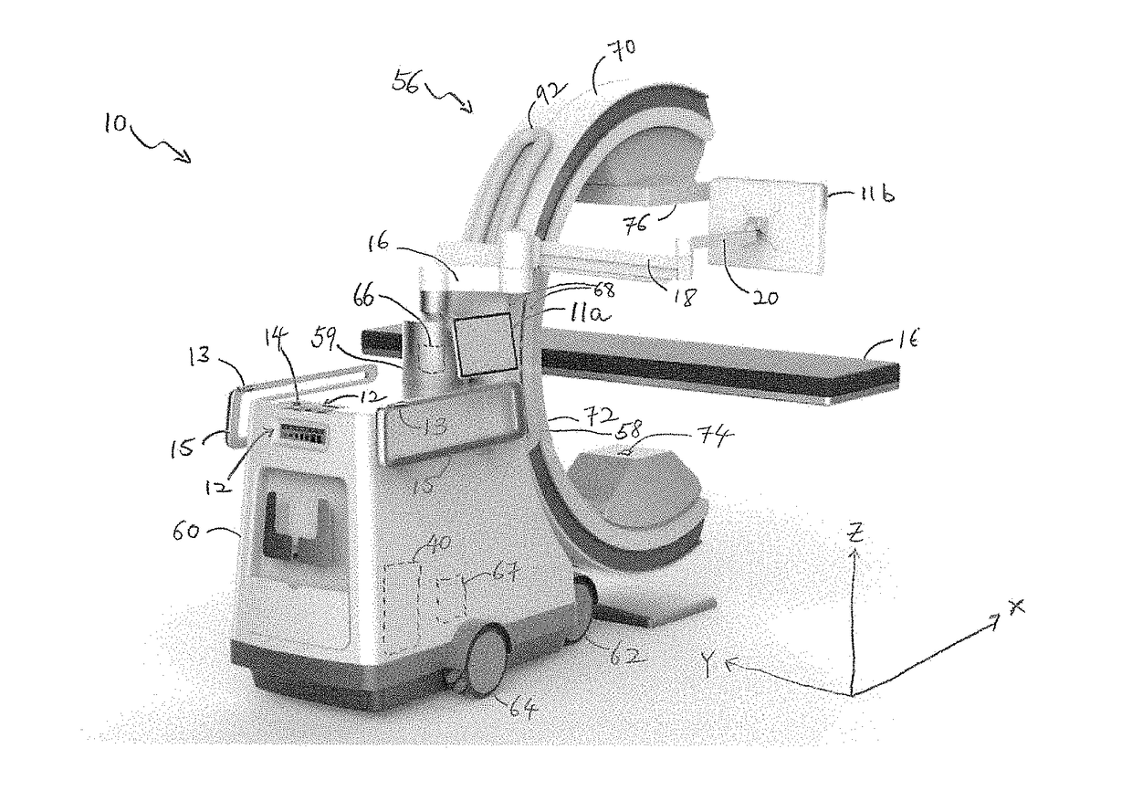
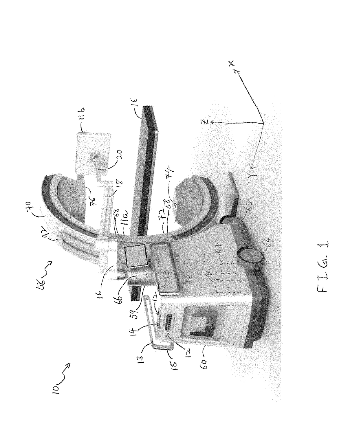
[0032]Turning now to the drawing, FIG. 1 is a schematic diagram showing an imaging system 10, such as a computerized tomographic (CT) x-ray scanner, in accordance with one embodiment of the disclosure. The imaging system 10 includes a movable station 60 and a gantry 56. The movable station includes a vertical shaft 59 and a gantry mount 58 which is rotatably attached to the vertical shaft. The movable station 60 includes two front omni-directional wheels 62 and two rear omni-directional wheels 64, which together provide movement of the movable station 60 in any direction in an X-Y plane. The horizontal X-Y plane is depicted in the Cartesian coordinate system X, Y axes...


PUM


Abstract

Medical imaging devices, systems, and methods thereof. The medical imaging system may include a movable station and a gantry. The movable station includes a gantry mount rotatably attached to the gantry. The gantry includes an outer C-arm slidably mounted to and operable to slide relative to the gantry mount, an inner C-arm slidably coupled to the outer C-arm and, an imaging signal transmitter and sensor attached to the C-arms. The two C-arms work together to provide a full 360 degree rotation of the imaging signal transmitter. The movable station may include a motion control system and an imaging control system. In embodiments, the motion control system includes omni-directional wheels for precision controlled-movement of the movable station.

Description

CROSS REFERENCE TO RELATED APPLICATION[0001]This application is a continuation-in-part of U.S. patent Ser. No. 15 / 014,083, filed Feb. 3, 2016, which is hereby incorporated by reference in its entirety for all purposes.TECHNICAL FIELD[0002]The present disclosure relates to medical imaging systems, and more particularly, controlled movement of the imaging system or components thereof.BACKGROUND OF THE DISCLOSURE[0003]Healthcare practices have shown the tremendous value of three-dimensional imaging such as computed tomography (CT) imaging, as a diagnostic tool in the Radiology Department. These imaging systems generally contain a fixed bore into which the patient enters from the head or foot. Other areas of care, including the operating room, intensive care departments and emergency departments, rely on two-dimensional imaging (fluoroscopy, ultrasound, 2-D mobile X-ray) as the primary means of diagnosis and therapeutic guidance.[0004]While mobile solutions for ‘non-radiology department...

Claims


Application Information

Patent Timeline
Patent Type & Authority Applications(United States)
IPC IPC(8): A61B6/00A61B5/055A61B6/03
CPCA61B6/4441A61B6/032A61B6/4405A61B5/055A61B6/4085A61B6/485A61B6/547A61B6/56H02G11/006
Inventor JOHNSON, NORBERTSTEVENS, ROBERTSALEM, HISHAMCHENG, YUAN
Owner GLOBUS MEDICAL INC
Why Eureka
Try Eureka