
High-resolution computed tomography or c-arm imaging

a computed tomography and high-resolution technology, applied in the field of high-resolution computed tomography imaging, can solve the problems of significant increase in hardware cost, and the difficulty of designing a scanner that is both low-cost and can opera

Inactive Publication Date: 2017-08-03
GENERAL ELECTRIC CO
View PDF28 Cites 8 Cited by
  • Summary
  • Abstract
  • Description
  • Claims
  • Application Information

AI Technical Summary

Benefits of technology

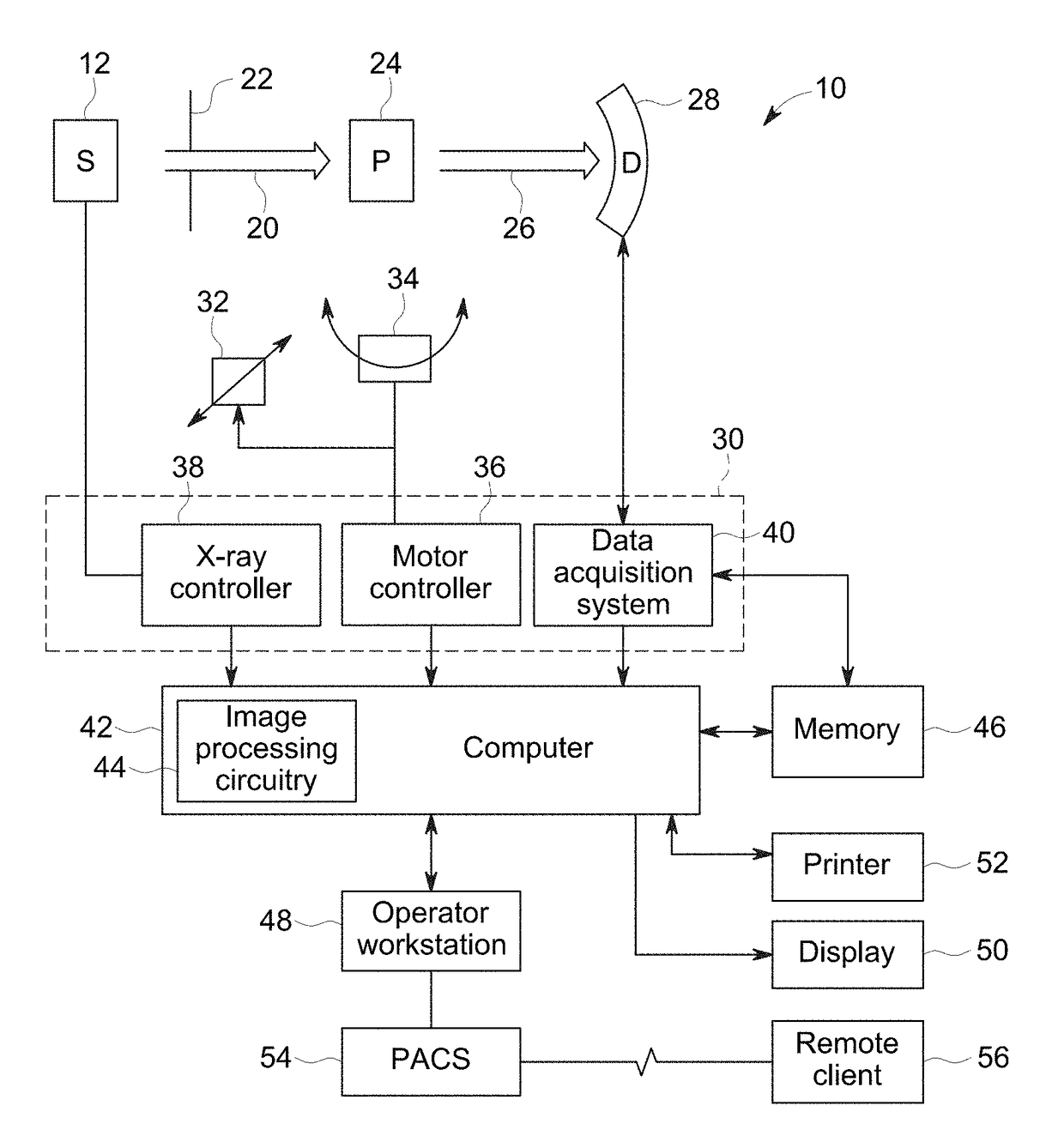
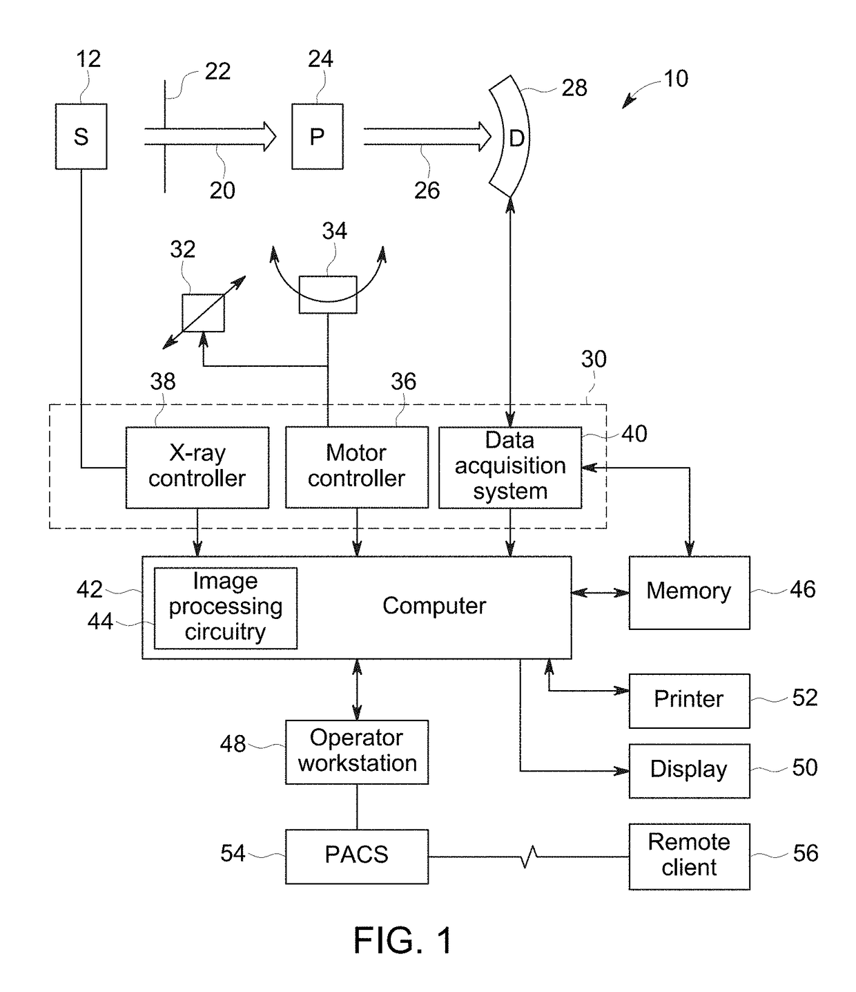
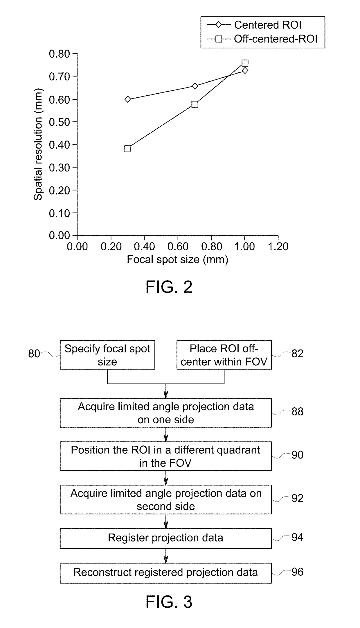
This patent presents a method and system for generating high-resolution images using X-ray imaging technology. The method involves specifying a smaller focal spot size for the X-ray source than the size of the detector cells, positioning the region-of-interest being imaged offset from the iso-center of the field-of-view, and acquiring a set of projection data over a limited angular range during rotation of the X-ray source and detector. The registered and reconstructed projection data is then used to generate the high-resolution image. The technical effect of this invention is improved image quality and resolution using X-ray imaging technology.

Problems solved by technology

However, using smaller detector cell sizes significantly increases the cost of the hardware.
Overall, it is challenging to design a scanner that is both low-cost and can operate with a combination of low-dose, high-spatial resolution and low-noise.

Method used


Image

  • High-resolution computed tomography or c-arm imaging
  • High-resolution computed tomography or c-arm imaging
  • High-resolution computed tomography or c-arm imaging

Examples


Embodiment Construction

[0020]One or more specific embodiments will be described below. In an effort to provide a concise description of these embodiments, not all features of an actual implementation are described in the specification. It should be appreciated that in the development of any such actual implementation, as in any engineering or design project, numerous implementation-specific decisions must be made to achieve the developers' specific goals, such as compliance with system-related and business-related constraints, which may vary from one implementation to another. Moreover, it should be appreciated that such a development effort might be complex and time consuming, but would nevertheless be a routine undertaking of design, fabrication, and manufacture for those of ordinary skill having the benefit of this disclosure.

[0021]While the following discussion is generally provided in the context of medical imaging, it should be appreciated that the present techniques are not limited to such medical ...


PUM


Abstract

A high-resolution imaging approach is described. The described approach includes use of a small focal spot size and positioning of the patient offset from the center of the imaging volume. The off-center displacement is combined with a small focal spot size and with modified image reconstruction methods to provide high intrinsic spatial resolution without hardware changes to the imaging system.

Description

BACKGROUND[0001]The subject matter disclosed herein relates to high resolution computed tomography imaging.[0002]Non-invasive imaging technologies allow images of the internal structures or features of a patient to be obtained without performing an invasive procedure on the patient. In particular, such non-invasive imaging technologies rely on various physical principles, such as the differential transmission of X-rays through the target volume or the reflection of acoustic waves, to acquire data and to construct images or otherwise represent the observed internal features of the patient.[0003]For example, in computed tomography (CT) and other X-ray based imaging technologies, X-ray radiation passes through a subject of interest, such as a human patient, and a portion of the radiation impacts a detector where the image data is collected. In digital X-ray systems a photodetector produces signals representative of the amount or intensity of radiation impacting discrete pixel regions o...

Claims


Application Information

Patent Timeline
Patent Type & Authority Applications(United States)
IPC IPC(8): A61B6/03A61B6/04A61B6/00
CPCA61B6/035A61B6/04A61B6/54A61B6/4021A61B6/025A61B6/027A61B6/032A61B6/5205
Inventor DE MAN, BRUNO KRISTIAAN BERNARDFU, LINFRONTERA, MARK ALAN
Owner GENERAL ELECTRIC CO
Learn More