Lens manufacturing method, lens, and lens holding device
a manufacturing method and lens technology, applied in the direction of manufacturing tools, optical surface grinding machines, grinding machine components, etc., can solve the problems of difficult to machine non-planar lenses along with both surfaces with high accuracy, relative surface shape error on the front and reverse surfaces of lenses, and achieve excellent optical transmission performance
Active Publication Date: 2017-06-29
FUJIFILM CORP
View PDF3 Cites 2 Cited by
- Summary
- Abstract
- Description
- Claims
- Application Information
AI Technical Summary
Benefits of technology
[0027]According to the lens manufacturing method, the lens, and the lens holding device o
Problems solved by technology
For example, in ordinary spherical lenses, a saddle-type error (a so-called astigmatism error) may be generated in a planar shape, and aberration is generated in a transmission wave surface due to a difference in surface shape accuracy from a reverse surface.
However, in the above-described related-art techniques, it was difficult to machine non-planar lenses along with both surfaces with high accuracy.
For example, in the technique described in the
Method used
View moreImage
Smart ImageViewing Examples

Examples
 PUM
 Abstract
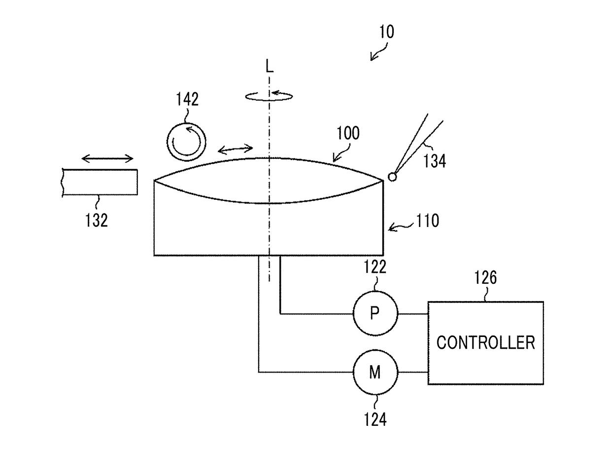
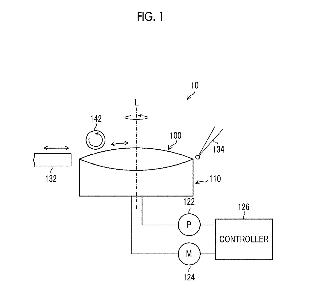
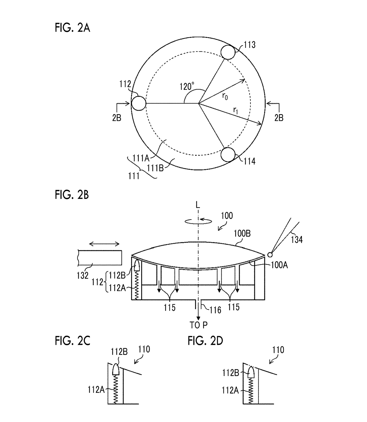
A lens manufacturing method including a holding step of holding a lens in a lens holding fixture, and a machining step of machining a surface to be machined in the held lens. A reverse surface of the surface to be machined is machined into a non-planar shape with a first surface shape error. A lens holding surface of the lens holding fixture is machined into the same shape as the non-planar shape with a second surface shape error smaller than the first surface shape error. In the holding step, the reverse surface is brought into surface contact with the holding surface in imitation of the holding surface to correct the shape of the lens such that the reverse surface runs along the holding surface. In the machining step, the surface to be machined is machined in a state where the correction has been made by the holding step.
Description
CROSS-REFERENCE TO RELATED APPLICATIONS[0001]The present application is a Continuation of PCT International Application No. PCT / JP2015 / 070567 filed on Jul. 17, 2015 claiming priority under 35 U.S.C §119(a) to Japanese Patent Application No. 2014-202531 filed on Sep. 30, 2014. Each of the above applications is hereby expressly incorporated by reference, in their entirety, into the present application.BACKGROUND OF THE INVENTION[0002]1. Field of the Invention[0003]The present invention relates to a lens manufacturing method, a lens, and a lens holding device, and particularly, to a lens manufacturing method for grinding and polishing a lens, a lens manufactured through grinding and polishing, and a lens holding device used for manufacturing such a lens.[0004]2. Description of the Related Art[0005]When objects to be machined, such as lenses or semiconductor wafers, are grinded and polished, an object to be machined is fixed by bonding a reverse surface of the object to be machined to a...
Claims
Login to View More Application Information
Patent Timeline
 IPC IPC(8): B24B13/01B24B41/06
CPCB24B41/06B24B13/01B24B13/005B24B49/04B24B49/06
Inventor HIRAKI, YASUHITOITO, KENJIWATANABE, SEIICHI
Owner FUJIFILM CORP
Features
- R&D
- Intellectual Property
- Life Sciences
- Materials
- Tech Scout
- Unparalleled Data Quality
- Higher Quality Content
- 60% Fewer Hallucinations
Learn More Browse by: Latest US Patents, China's latest patents, Technical Efficacy Thesaurus, Application Domain, Technology Topic, Popular Technical Reports.
© 2025 PatSnap. All rights reserved.Legal|Privacy policy|Modern Slavery Act Transparency Statement|Sitemap|About US| Contact US: help@patsnap.com