
Method and apparatus for cleaning a contaminated air stream

a technology of contaminated air and air stream, which is applied in the direction of gaseous fuels, separation processes, fuels, etc., can solve the problems of inhibiting most biological activity, reducing the ph of the system, and limited capacity of biological waste treatment systems to handle variable loads, etc., to improve efficiency and elimination capacity, improve the utilization of heavier media, and increase the face velocity of air

Active Publication Date: 2017-06-22
ANUA CLEAN AIR INT LTD
View PDF3 Cites 8 Cited by
  • Summary
  • Abstract
  • Description
  • Claims
  • Application Information

AI Technical Summary

Benefits of technology

The patent is about using rubber material to remove sulfur from contaminated gas. The rubber material is made from used vehicle tires and can be easily obtained. A multistage system is preferred over a single filter as it increases the efficiency and lifespan of the filter. The system also uses larger fans and a multi-compartment approach to improve the results and utilize more reactive polishing shells. Overall, the patent provides a cost-effective and efficient way to remove sulfur from gas.

Problems solved by technology

Biological waste treatment systems are limited in their ability to handle these variable loads.
One of the major problems with many prior art bio filtration systems is that while they are highly successful in removing H2S, the biological conversion of H2S generates H2SO which causes the pH of the system to decrease and if uncontrolled, it can fall to below 4.0 in turn causing inhibition of most biological activity, often referred to as “souring”.
While these approaches are reasonably successful, prolonged exposure to levels of H2S greater than the design level still results in souring which often necessitates pH adjustment.
A further problem with organic media bio filtration systems is that while they are often highly efficient at steady state loadings, the efficiency reduces as the loadings increase.
Needless to say, the necessity of dilution or reduction in flow rates will result in an increase in the size of bio filter with a corresponding increase in cost and in any event lead to more complex equipment to ensure that the difficulties of peak loadings are overcome.
Another major problem in the use of any biological system is that it is dependent on the activity of the microorganisms present in the system.

Method used


Image

  • Method and apparatus for cleaning a contaminated air stream
  • Method and apparatus for cleaning a contaminated air stream
  • Method and apparatus for cleaning a contaminated air stream

Examples


Embodiment Construction

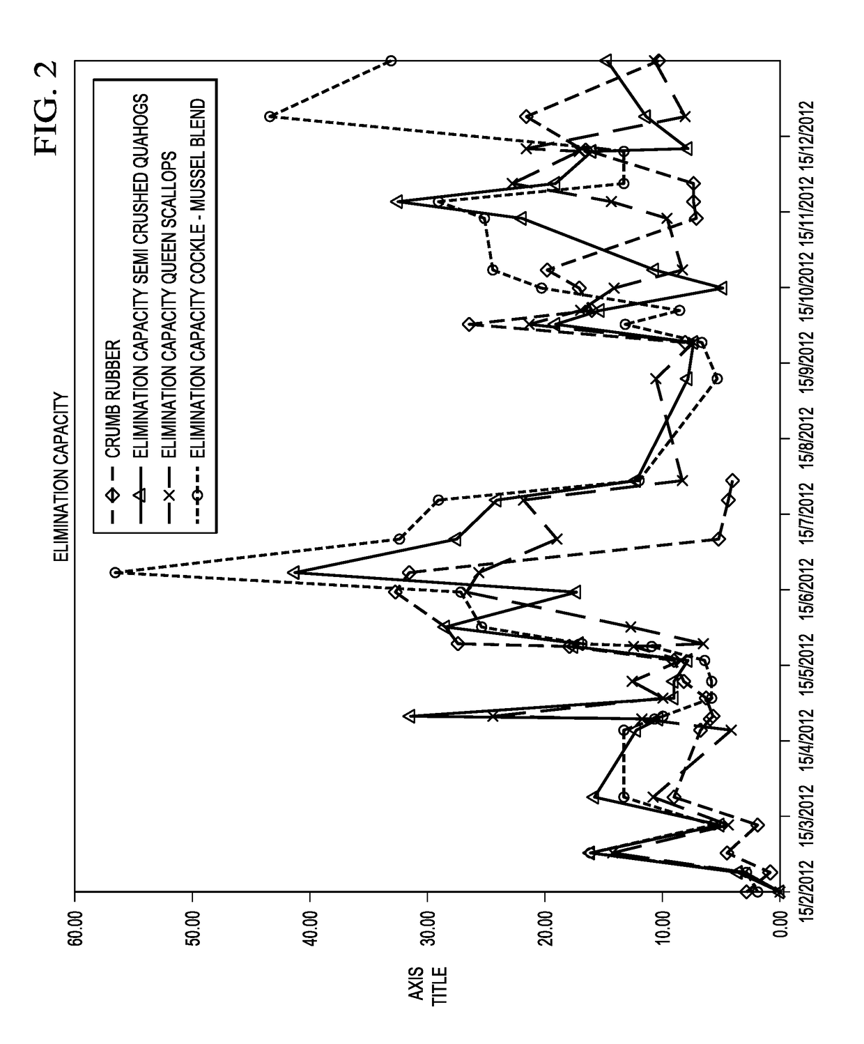
[0066]The following table lists the results of testing performed using various mixtures of marine shell material.

AverageAverageAverageLoadingEliminationRemovalm3 / m3 / CapacityMedia%hrg / m3 / hMussels / Queen72.6777.117.40ScallopsMussels / Cockles64.8085.817.10Mussels / Semi71.0068.614.85Crushed Quahogs

[0067]The mussel / queen scallop mix gave the highest elimination capacity followed by mussel / cockle and mussel / quahog. The multi pass or layered approach is superior to blending medias. Performance was improved by using a higher efficiency spiral nozzle.

[0068]The invention is not limited to the embodiment hereinbefore described, with reference to the accompanying drawings, which may be varied in construction and detail. It is appreciated that certain features of the invention, which are, for clarity, described in the context of separate embodiments, may also be provided in combination in a single embodiment. Conversely, various features of the invention which are, for brevity, described in the con...


PUM

PropertyMeasurementUnit
Volumeaaaaaaaaaa
Volumeaaaaaaaaaa
Volumeaaaaaaaaaa

Abstract

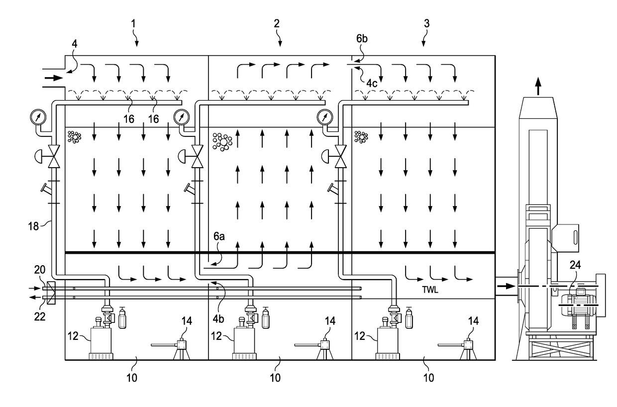
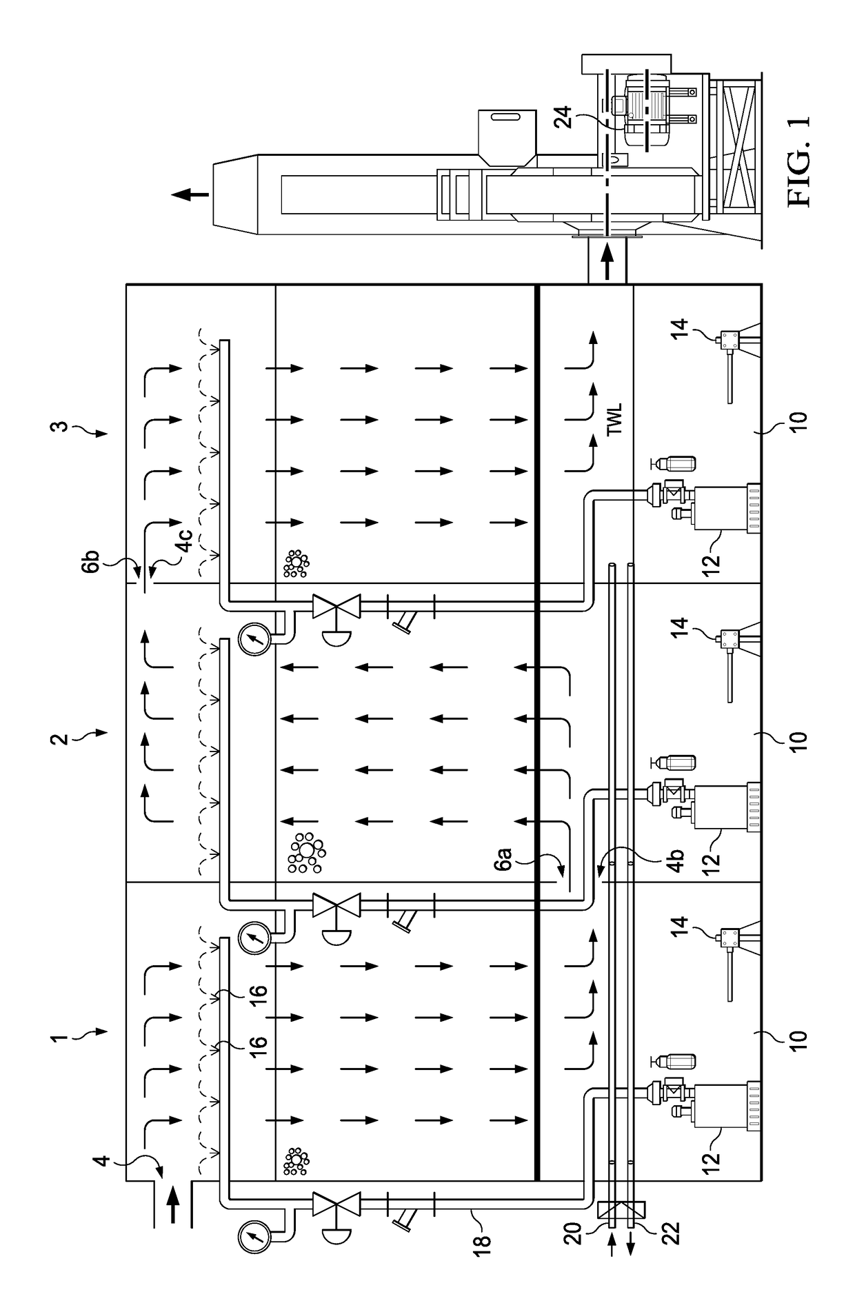
A method and apparatus for cleaning a contaminated air stream, the method comprising the step of passing the contaminated air stream through a multistage cleaning reactor, wherein at least two stages of the multistage cleaning reactor comprise marine shell material.

Description

FIELD OF THE INVENTION[0001]This invention relates to a method of cleaning a contaminated air stream to remove odours and volatile organic compounds (VOCs).BACKGROUND TO THE INVENTION[0002]The invention is suitable for treating waste air streams containing high concentrations of sulphur and other odorous compounds. The origins of the contaminated air stream may be from processing of municipal or industrial wastewater or treatment processes for the by-products of waste water treatment such as bio solids dewatering, drying, pasteurising or physical and chemical and thermal hydrolysis prior to digestion. Such waste air typically contains between 10% and 20% oxygen.[0003]The contaminants in the contaminated air stream may include reduced sulphur compounds such as hydrogen sulphide (H2S), volatile organic compounds and / or organic sulphur compounds. The apparatus 1 is suitable for removing contaminants from the contaminated air stream where the concentration of contaminants is high, for e...

Claims


Application Information

Patent Timeline
IPC IPC(8): B01D53/85B01D53/72B01D53/52B01D53/96B01D53/02
CPCB01D53/85B01D53/96B01D53/02B01D2253/10B01D53/72B01D2257/304B01D2257/708B01D53/52B01D53/84C10L3/103B01D2251/404B01D2251/606B01D2251/95B01D2256/245B01D2257/306B01D2257/55B01D2258/05B01D2258/06B01D2259/124Y02A50/20
Inventor PHILLIPS, JOHN PAUL
Owner ANUA CLEAN AIR INT LTD
Learn More