Gas liquefaction plant

Active Publication Date: 2017-06-08
JGC CORP
View PDF4 Cites 1 Cited by
  • Summary
  • Abstract
  • Description
  • Claims
  • Application Information

AI Technical Summary

Benefits of technology

The present invention simplifies the piping arrangement and reduces the installation space of a gas liquefaction plant by using multiple compressors for a refrigeration cycle. A precooling heat exchanging portion and an auxiliary heat exchanging portion are placed on one side of a pipe rack portion that holds a pipe assembly. On the other side of the pipe rack portion, a primary heat exchanging portion that liquefies the preliminarily-cooled raw gas is placed. Multiple compressors compress the preliminary refrigerant and the primary refrigerant subjected to heat exchange at the heat exchanging portions. This simplifies the installation process and reduces the cost of the gas liquefaction plant.

Problems solved by technology

The use of multiple smaller gas turbines in the layout disclosed in Patent Literature 1, however, makes the piping arrangement complex, requiring a wide space and increasing the size of the gas liquefaction plant.
Patent Literature 2 describes the technology involving multiple compressors driven by respective gas turbines in the refrigeration cycle for liquefying a natural gas, but does not disclose the technology for solving the problem confronted by the inventors.

Method used


Image

  • Gas liquefaction plant
  • Gas liquefaction plant
  • Gas liquefaction plant

Examples


Embodiment Construction

[0022]A facility for producing a liquefied natural gas (LNG), or a gas liquefaction plant, according to an embodiment of the present invention is described now.

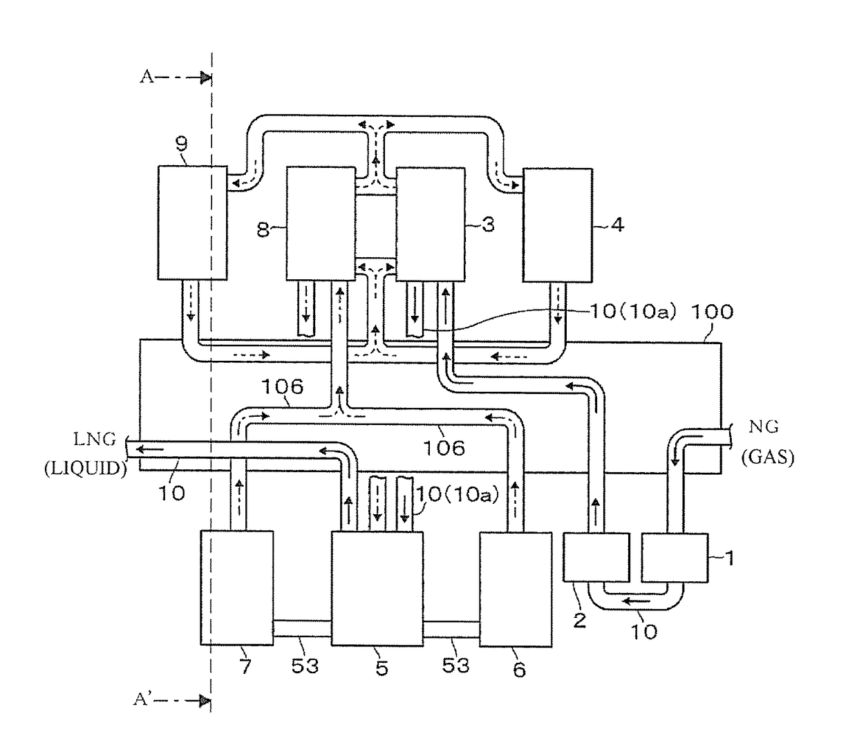
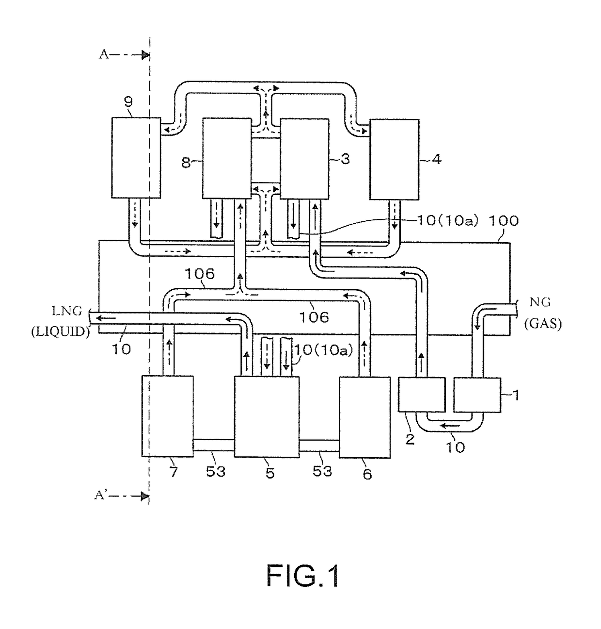
[0023]Firstly, referring to the plan view of FIG. 1, a schematic configuration of the LNG producing facility is described.

[0024]The description is given in order in which a natural gas (hereinafter referred to as a “NG”) is processed. A LNG producing facility includes an acid gas removing portion 1, a water removing portion 2, a precooling heat exchanging portion 3, and a liquefaction portion 5. The acid gas removing portion 1 removes an acid gas from a NG, which is a raw gas. The water removing portion 2 removes water from the NG. The precooling heat exchanging portion 3 preliminarily cools the NG subjected to preprocessing of acid gas removal and water removal and cools the resultant NG to a temperature within the range of approximately −20° C. to −70° C., for example, to an intermediate temperature within the range of −38°...


PUM


Abstract

In a gas liquefaction plant that produces a liquefied gas by liquefying a raw gas, a pipe rack portion in which an air-cooling heat exchanging system is disposed has a rectangular shape when viewed from above. A first compressor, a precooling heat exchanging portion, an auxiliary heat exchanging portion, and a fourth compressor are arranged in this order along one long side of the pipe rack portion. A second compressor, a primary heat exchanging portion, and a third compressor are arranged in this order along the other long side of the pipe rack portion. A pipe that carries the raw gas cooled at the precooling heat exchanging portion is connected to the primary heat exchanging portion across the pipe rack portion. A pipe that carries a primary refrigerant compressed at the second and third compressors is connected to the auxiliary heat exchanging portion across the pipe rack portion.

Description

TECHNICAL FIELD[0001]The present invention relates to a facility for producing a liquefied gas by liquefying a raw gas.BACKGROUND ART[0002]The process of producing a liquefied natural gas includes a step of preprocessing a natural gas, such as removal of acid gas and water, a subsequent step of preliminarily cooling the natural gas to, for example, approximately −40° C. using a precooling refrigerant, and a subsequent step of removing a heavy gas from the natural gas and liquefying the natural gas by cooling the gas to a temperature within the range of, for example, −155° C. to −158° C. using a primary refrigerant. Examples usable as a precooling refrigerant include a refrigerant containing propane as a main component, and examples usable as a primary refrigerant include a mixed refrigerant containing a mixture of methane, ethane, propane, and nitrogen.[0003]These refrigerants are circulated in a vapor compression refrigeration cycle. In the refrigeration cycle, the refrigerants in ...

Claims


Application Information

Patent Timeline
IPC IPC(8): F25J1/02F25J1/00
CPCF25J1/0259F25J1/0022F25J1/0216F25J1/0292F25J1/0294F25J1/0283F25J2270/60F25J2220/68F25J2220/64F25J2290/60F25J2290/42F25J2270/66F25J2220/66F25J1/0052F25J1/0087F25J1/0296
Inventor TAKEZAWA, NAOYUKIAKIYAMA, SHIGERUWAKAMATSU, YOSHIHISA
Owner JGC CORP
Why Eureka
Try Eureka