Regeneration of a hydrogen impurity trap using the heat exiting a hydride tank

a technology of hydride tank and heat exiting, which is applied in the direction of fixed capacity gas holders, gas/liquid distribution and storage, gas treatment, etc., can solve the problems of degrading the storage performance of hydrides, inapplicable to large amounts of hydrogen to be purified, and done at the expense of weigh

Active Publication Date: 2017-06-08
COMMISSARIAT A LENERGIE ATOMIQUE ET AUX ENERGIES ALTERNATIVES
View PDF0 Cites 0 Cited by
  • Summary
  • Abstract
  • Description
  • Claims
  • Application Information

AI Technical Summary

Benefits of technology

[0027]In particular, an object of the invention is to provide such a solution, which makes it possible:
[0029]to obtain good purification and regeneration efficiency, while at the same time having a good storage and destocking yield,

Problems solved by technology

However, this is done at the expense of the weight, since on balance it is necessary to add the weight of the hydride material into which the hydrogen becomes inserted.
Thus, a low concentration of these compounds in hydrogen significantly degrades the storage performance of the hydrides.
This type of trap must be returned to the supplier to be regenerated, which makes it inapplicable for large amounts of hydrogen to be purified.
Two regeneration modes are commonly used:temperature modulation: a source of external energy (circulation of oil or electrical resistance) is used to heat the material and regenerate it, which greatly complicates the system and consumes energy,pressure modulation: the regeneration is performed without a temperature increase but by lowering the pressure of gas around the material, which does not make it possible to exploit the full capacity of the material.
Devices using two traps are bulky and require greater investment.
The regeneration phase of the sieves is, however, problematic since it is based on the pressure difference between the absorption of hydrogen and the desorption to clean the filter and to take away for desorption the water adsorbed in the molecular sieves.
This well-known process does not operate if the inlet pressure is only slightly higher (or lower than) than the outlet pressure of the tank and it is then impossible to regenerate the filter, which becomes saturated with water and no longer protects the hydride tank from humidity.
This method is efficient, but gives rise to a loss of yield since electrical energy must be drawn from the battery to heat the molecular sieves.

Method used


Image

  • Regeneration of a hydrogen impurity trap using the heat exiting a hydride tank
  • Regeneration of a hydrogen impurity trap using the heat exiting a hydride tank
  • Regeneration of a hydrogen impurity trap using the heat exiting a hydride tank

Examples


Embodiment Construction

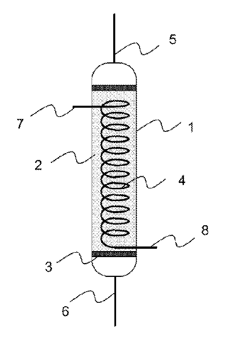
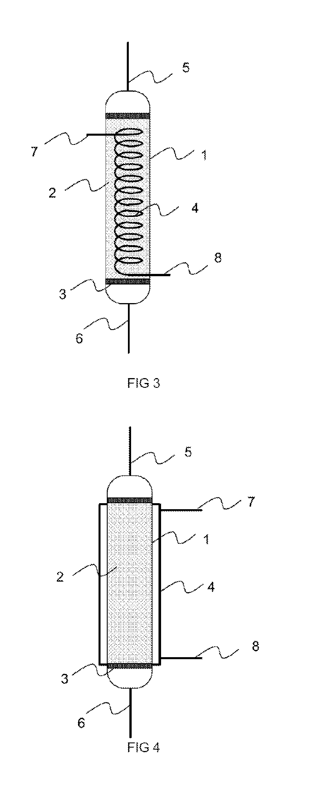
[0070]In general, and with reference to FIGS. 3 to 10, the invention relates to a process and an installation for storing and destocking hydrogen in a hydride tank 10. The hydride tank 10 may especially comprise magnesium-based hydrides, without this limiting the field of application.

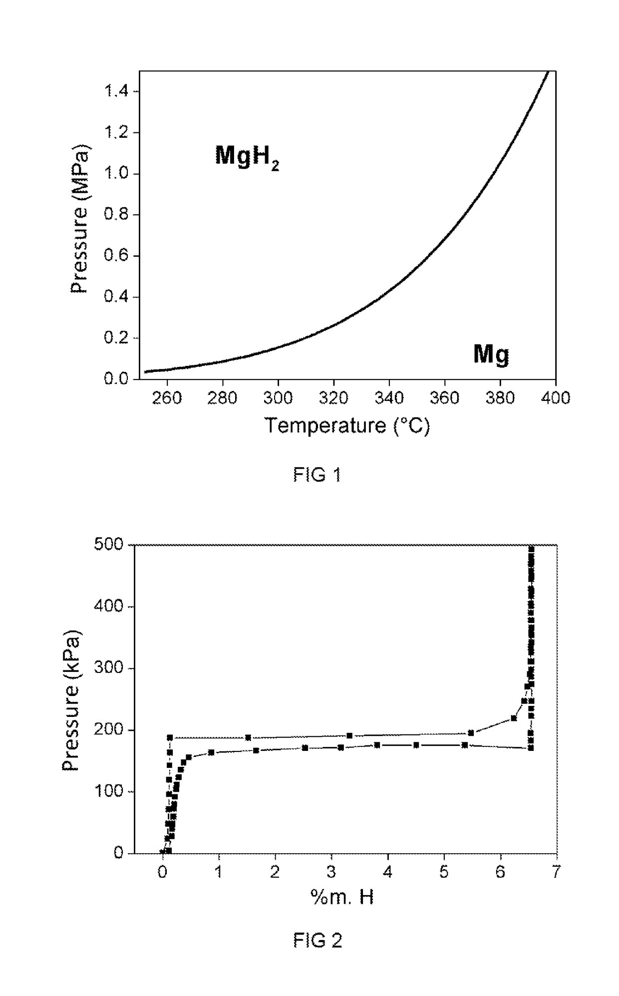
[0071]The solution proposed is particularly suited to hydrides operating at low pressure (1 to 20 bar) and at high temperature (between 200 and 400° C.). These hydrides must, by their nature, be brought to high temperature in order to be able to release the stored hydrogen. The hydrogen then exits hot from the tank. This may concern the field of hydrogen storage for feeding fuel cells, hydrogen turbines, heat engines or the industry using hydrogen.

[0072]The process comprises a purification step performed on at least one trap that filters out the impurities contained in the hydrogen entering the tank 10 for storage and a step of regenerating said at least one trap, using the heat carried by the hydrogen ...


PUM

PropertyMeasurementUnit
pressuresaaaaaaaaaa
temperatureaaaaaaaaaa
pressureaaaaaaaaaa

Abstract

The storing and destocking of hydrogen in a hydride tank (10) comprises purification performed in at least one trap (1, 1A, 1B) filtering the impurities contained in the hydrogen entering the tank to be stored and regeneration of said at least one trap, using the heat carried by the hydrogen exiting the tank after it has been destocked.

Description

TECHNICAL FIELD OF THE INVENTION[0001]The invention relates to a process for storing and destocking hydrogen in a hydride tank, comprising a purification step performed on at least one trap that filters out the impurities contained in the hydrogen entering the tank for its storage.[0002]A subject of the invention is also an installation for storing and destocking hydrogen, comprising a hydride tank into which the hydrogen enters to be stored and from which it exits to be destocked, and at least one trap that filters out the impurities contained in the hydrogen entering the tank for storage.PRIOR ART[0003]Hydrogen storage is a very important point in the development of a hydrogen-based energy vector chain. It is fundamental to store it for applications which need to be transported and it is very advantageous to know how to store it for applications with intermittent primary energy.[0004]The storage of hydrogen may take place in gaseous form, by compressing it up to pressures of 700 b...

Claims


Application Information

Patent Timeline
Patent Type & Authority Applications(United States)
IPC IPC(8): B01D53/04F17C11/00
CPCB01D53/0438B01D53/0446F17C11/005B01D2253/1126B01D2253/116F17C2221/012B01D2256/16B01D2257/80B01D2259/40098B01D2259/4525B01D2253/108C01B3/0005C01B3/50C01B3/56B01D53/0462B01D2259/40052B01D2259/40088Y02E60/32
Inventor CHAISE, ALBIN
Owner COMMISSARIAT A LENERGIE ATOMIQUE ET AUX ENERGIES ALTERNATIVES
Why Eureka
Try Eureka