
Optical interconnection methods and systems exploiting mode multiplexing

a technology of optical interconnection and mode multiplexing, applied in the field of optical interconnection networks, can solve the problems of increasing the amount of data being uploaded and downloaded every second on the internet, and increasing the difficulty of synchronizing and synchronizing

Active Publication Date: 2017-06-01
MCGILL UNIV +1
View PDF1 Cites 6 Cited by
  • Summary
  • Abstract
  • Description
  • Claims
  • Application Information

AI Technical Summary

Benefits of technology

This approach reduces latency, lowers power consumption, and decreases costs while providing scalable and flexible optical interconnection solutions for data centers, enabling efficient data transfer between servers and within data centers.

Problems solved by technology

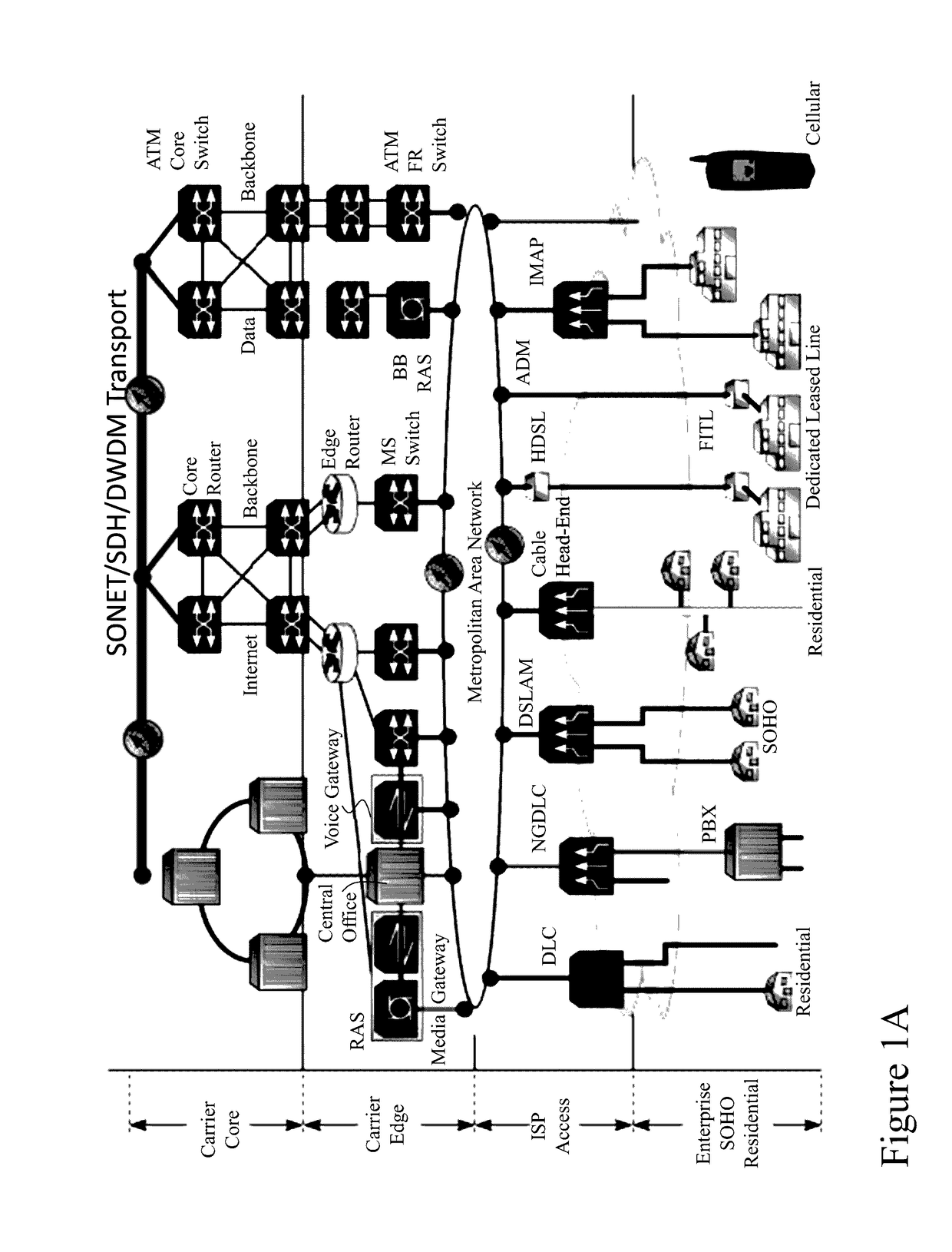
Further, with almost three billion Internet users accessing these websites, including a growing amount of high bandwidth video, there is a massive amount of data being uploaded and downloaded every second on the Internet.
At the same time consumers' expectations of download / upload speeds and latency in accessing content provide additional pressure.
However, within the server the electrical interconnection networks also suffer issues when scaling to a large number of processors due to the server level interconnections albeit differing in several aspects.
Simple topologies, such as a chip-global bus, exhibit high latency, require power-hungry repeaters, and occupy large footprint.
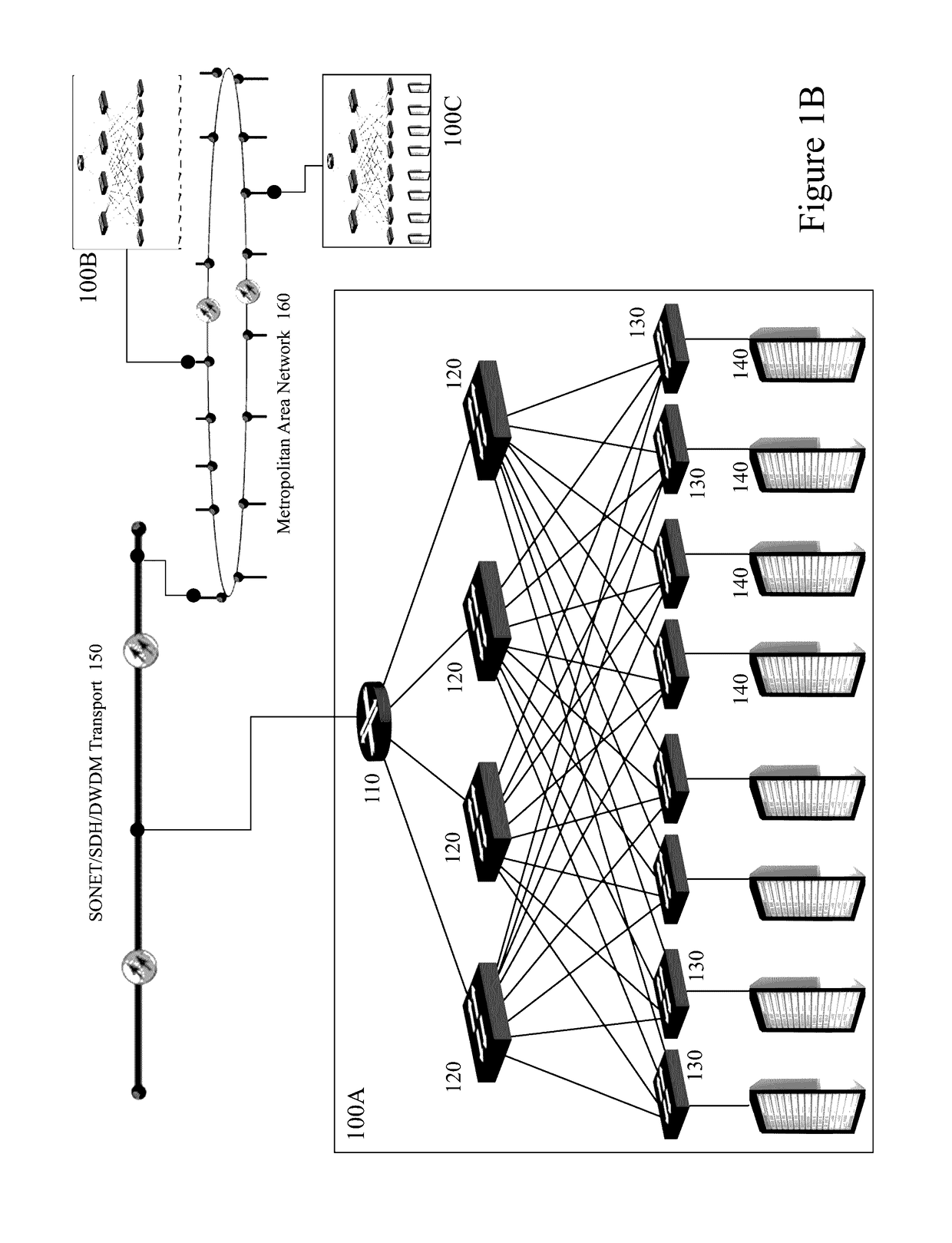
Still, these networks just like the spline-leaf networks connecting servers require the signal to cross multiple hops for connecting distant cores and are prone to contention between concurrent message transmissions, both leading to increased latency and power consumption.
Such optical space switching architectures required multiple switching elements, leading to increased power consumption and footprint issues.

Method used


Image

  • Optical interconnection methods and systems exploiting mode multiplexing
  • Optical interconnection methods and systems exploiting mode multiplexing
  • Optical interconnection methods and systems exploiting mode multiplexing

Examples


Embodiment Construction

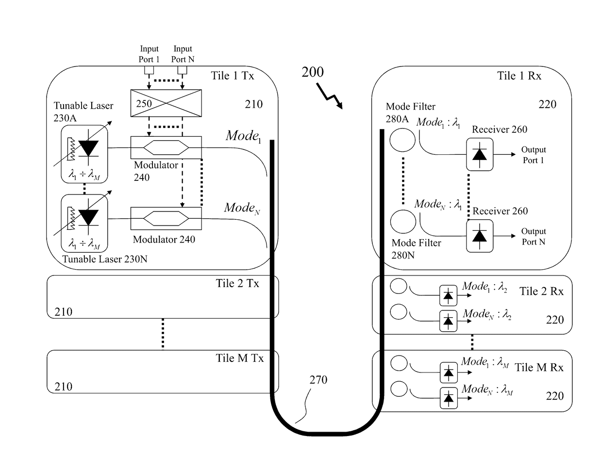
[0052]The present invention is directed to optical interconnection networks and more particularly to circuit board level, interchip, and intrachip optical interconnections and networks.

[0053]The ensuing description provides exemplary embodiment(s) only, and is not intended to limit the scope, applicability or configuration of the disclosure. Rather, the ensuing description of the exemplary embodiment(s) will provide those skilled in the art with an enabling description for implementing an exemplary embodiment. It being understood that various changes may be made in the function and arrangement of elements without departing from the spirit and scope as set forth in the appended claims.

[0054]A “tunable laser” as used herein, and throughout this disclosure, refers to a laser whose wavelength of operation can be altered in a controlled manner. This includes, but is not limited to, lasers where the optical length of the cavity can be modified and thus continuously tuned over a wavelength...


PUM


Abstract

Optical solutions to address and overcome the issues of superseding / replacing electrical interconnection networks have generally exploited some form of optical space switching. Such optical space switching architectures required multiple switching elements, leading to increased power consumption and footprint issues. Accordingly, it would be beneficial for new optical, e.g. fiber optic or integrated optical, interconnection architectures to address the traditional hierarchal time-division multiplexed (TDM) space based routing and interconnection to provide reduced latency, increased flexibility, lower cost, and lower power consumption. Accordingly, it would be beneficial to exploit networks operating in multiple domains by overlaying mode division multiplexing to provide increased throughput in bus, point-to-point networks, and multi-cast networks, for example, discretely or in combination with wavelength division multiplexing.

Description

CROSS-REFERENCE TO RELATED APPLICATIONS[0001]This patent application also claims the benefit of U.S. Provisional Patent Applications 62 / 056,650 filed Sep. 29, 2014 entitled “Mode Multiplexing Optical Interconnection Methods and Systems”, the entire contents of which are incorporated herein by reference.FIELD OF THE INVENTION[0002]This invention relates to optical interconnection networks and more particularly to circuit board level, interchip, and intrachip optical interconnections and networks.BACKGROUND OF THE INVENTION[0003]Optical fiber communications is seen as one of the most reliable telecommunication technologies to achieve consumers' needs for present and future applications. It is reliable in handling and transmitting data through hundreds of kilometers with an acceptable bit error rate and today, optical fiber communication dominates as the physical medium for medium and long distance data transmission systems and telecommunications networks. At the same time optical fibe...

Claims


Application Information

Patent Timeline
Patent Type & Authority Applications(United States)
IPC IPC(8): H04J14/04H04B10/2581H04J14/02H04Q11/00G02B6/293G02B6/12
CPCH04J14/04G02B6/2938G02B6/12004H04Q2011/0024H04Q11/0005H04B10/2581H04Q2011/0016H04J14/02H04J14/028H04J14/0305
Inventor LIBOIRON-LADOUCEUR, ODILEANDRIOLLI, NICOLACERUTTI, ISABELLAVELHA, PHILIPPE
Owner MCGILL UNIV
Learn More