Electrical junction box and connector housing
- Summary
- Abstract
- Description
- Claims
- Application Information
AI Technical Summary
Benefits of technology
Problems solved by technology
Method used
Image
Examples
embodiment 1
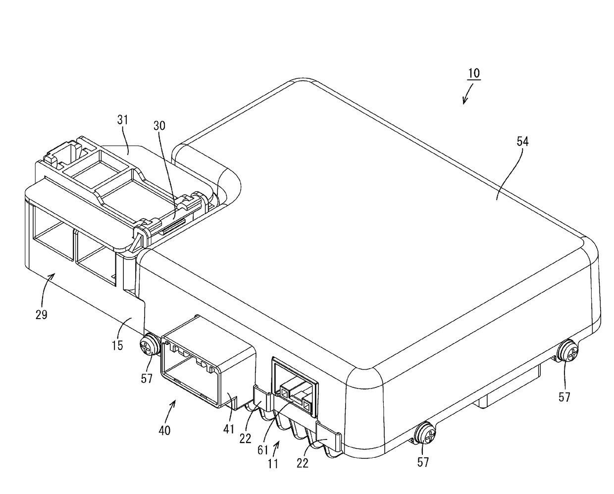
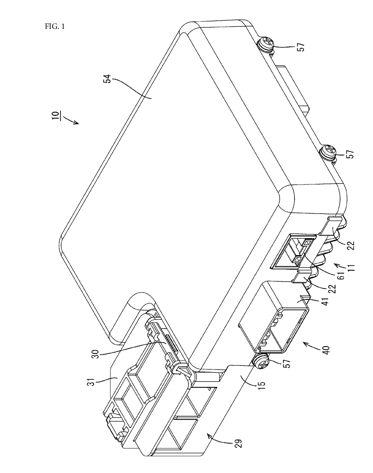
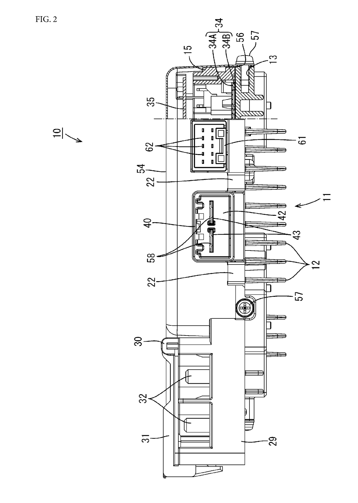
[0044]Hereinafter, Embodiment 1 will be described with reference to FIGS. 1 to 9.
[0045]An electrical junction box 10 is arranged, for example, in a power supply path between a power source such as a battery of a vehicle such as an electric automobile or a hybrid automobile, and a load constituted by a vehicle-mounted electrical equipment such as a lamp, a drive motor, or the like, and can be used, for example, for a DC-DC converter, an inverter, and the like. In the description below, the vertical direction will be indicated using the direction in FIG. 2 as a reference, and the front-rear direction will be described taking the left side in FIG. 3 as a front direction and the right side as a rear direction.
Electrical Junction Box 10
[0046]As shown in FIG. 2, the electrical junction box 10 includes a heat dissipation member 11, a base member 15 made of synthetic resin placed on the upper face of the heat dissipation member 11, two circuit boards 34 and 35 fastened to the base member 15...
embodiment 2
[0078]Hereinafter, Embodiment 2 will be described with reference to FIG. 10. Embodiment 2 is different from Embodiment 1 in that it includes a catch portion 70 having a shape that is different from that of the catch portion 48. The other aspects of the configuration are the same as those in Embodiment 1, and thus the same constituent elements are denoted by the same reference numerals, and their description has been omitted.
[0079]As shown in FIG. 10, the catch portion 70 includes a pair of upper and lower gripping portions 71 and 72 that grip the circuit board 35 from both sides. The pair of gripping portions 71 and 72 are in the shape of plates. The upper gripping portion 71 horizontally extends along relatively high positions, continuing to the upper face of the receiving portion 45, and includes a contact point portion 71A projecting downward. The lower gripping portion 72 horizontally extends along positions below the gripping portion 71 via a predetermined gap. The predetermine...
embodiment 3
[0082]A technique disclosed in this specification relates to an electrical junction box.
[0083]Conventionally, electronic controllers are known in which a circuit board unit having electronic circuit portions assembled therein is accommodated in a metal casing (see JP 2001-223489A). The casing includes a frame in the shape of a flat box and a lid member that covers the opening of the frame, and is configured so as to be tightly closed when the frame and the lid member are fastened with screws to each other.
[0084]Incidentally, the metal casing is relatively thin, and thus, when it is mounted in a vehicle such as an automobile, it easily vibrates, so that the frame and the lid member may hit each other at portions other than the portions having the screws, which may generate abnormal noise. In particular, for example, when an opening is provided through part of the casing such as a portion around a connector or the like, the peripheral edge of the opening has a much lower rigidity, abn...
PUM
 Abstract
Description
Claims
Application Information
 - R&D
- Intellectual Property
- Life Sciences
- Materials
- Tech Scout
- Unparalleled Data Quality
- Higher Quality Content
- 60% Fewer Hallucinations
Browse by: Latest US Patents, China's latest patents, Technical Efficacy Thesaurus, Application Domain, Technology Topic, Popular Technical Reports.
© 2025 PatSnap. All rights reserved.Legal|Privacy policy|Modern Slavery Act Transparency Statement|Sitemap|About US| Contact US: help@patsnap.com


