
Membrane Electrode Assembly

a membrane electrode and electrode technology, applied in the direction of electrical equipment, cell components, fuel cells, etc., can solve the problems of irreversible damage to the catalyst layer/electrode structure, temporary undesirable electrochemical reactions, and irreversible damage to the anode structure, so as to improve the tolerance to degradation, reduce oxidative corrosion, and improve the effect of toleran

Active Publication Date: 2017-06-01
JOHNSON MATTHEY HYDROGEN TECH LTD
View PDF4 Cites 2 Cited by
  • Summary
  • Abstract
  • Description
  • Claims
  • Application Information

AI Technical Summary

Benefits of technology

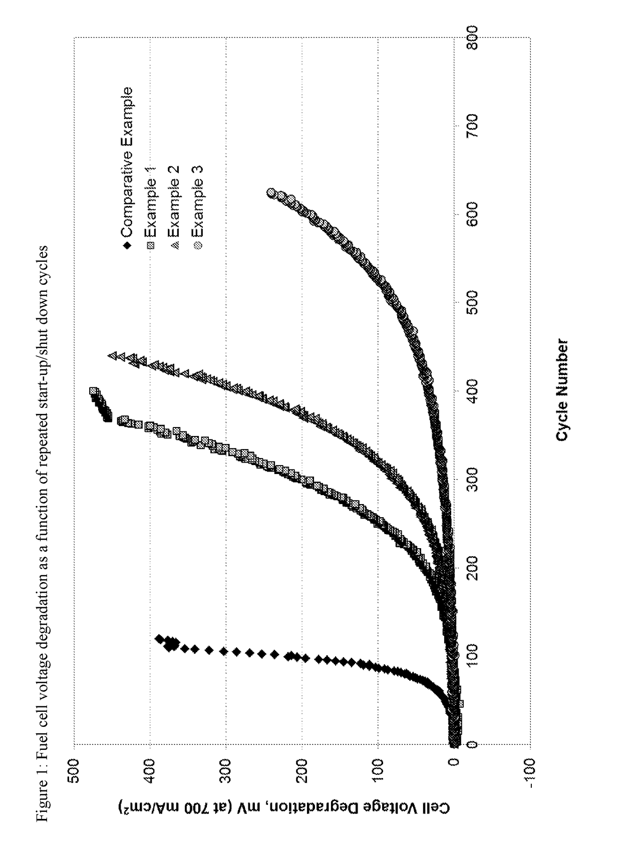
The present invention provides a catalysed membrane and membrane electrode assembly that can tolerate degradation caused by start-up / shut-down mechanisms without compromising performance. The assembly includes a specific anode electrocatalyst layer that reduces oxidative corrosion of the cathode carbon support in real-life operational situations, leading to a more durable and longer lifetime for the catalysed membrane or membrane electrode assembly.

Problems solved by technology

High electrochemical potentials can occur in a number of real-life operational situations and in these circumstances can cause irreversible damage to the catalyst layer / electrode structure, due to corrosion of any carbon present in the layer (such as the support material for the catalyst) and loss of active surface area of the nanoparticulate electrocatalyst metal due to various metal sintering degradation mechanism that occur during high potential excursions.
This then leads to temporary undesirable electrochemical reactions taking place in order to maintain generation of an electrical current, such as carbon electro-oxidation at the anode which occurs at a higher potential than the oxygen reduction reaction at the cathode.
In such a cell reversal situation, the anode structure can be irreversibly damaged, even for very short durations of reversal, due to oxidation of the carbon and thus permanent degradation of the anode catalyst layer structure.
In such a start-up situation, the cathode structure can be irreversibly damaged, due to oxidation of the carbon and thus permanent degradation of the cathode catalyst layer structure.
A similar damaging electrochemical cell may also be set up on shut-down.
Although it may be possible to limit these processes from occurring by, for example, purging of the anode gas space with an inert gas such as nitrogen during shut-down, it is clearly not a practical or economically viable proposition to carry such an additional gas on-board a fuel cell powered vehicle.
These mitigation measures often lead to a lowering of the overall fuel cell performance due to compromises made in the properties of the electrocatalyst layers.

Method used


Image

  • Membrane Electrode Assembly

Examples


Embodiment Construction

[0034]Preferred and / or optional features of the invention will now be set out. Any aspect of the invention may be combined with any other aspect of the invention, unless the context demands otherwise. Any of the preferred or optional features of any aspect may be combined, singly or in combination, with any aspect of the invention, unless the context demands otherwise.

[0035]The present invention provides a catalysed membrane comprising:[0036](i) an ion-conducting membrane component having a first face and a second face, wherein the ion-conducting membrane component comprises an ion-conducting membrane;[0037](ii) an anode catalyst layer on the first face of the ion-conducting membrane component, wherein the anode catalyst layer comprises:[0038](a) a first electrocatalyst component comprising a first platinum-containing electrocatalyst and a first carbon support, wherein the first carbon support supports the first platinum-containing electrocatalyst;[0039]and wherein the electrochemic...


PUM

PropertyMeasurementUnit
surface areaaaaaaaaaaa
operating temperaturesaaaaaaaaaa
specific surface areaaaaaaaaaaa

Abstract

The invention includes a catalysed membrane and membrane electrode assembly. The membrane and membrane electrode assembly comprise an ion-conducting membrane component comprising an ion-conducting membrane, an anode catalyst layer, and a cathode catalyst layer. The anode catalyst layer comprises a first electrocatalyst component comprising a first platinum-containing electrocatalyst and a first carbon support. The first carbon support supports the first platinum-containing electrocatalyst, and the electrochemical platinum surface area in the anode catalyst layer is 5-100 cm2Pt / cm2 of the geometric electrode area of the anode catalyst layer. The cathode catalyst layer comprises a second electrocatalyst component and a second oxygen evolution reaction electrocatalyst. The second electrocatalyst component comprises a second platinum-containing electrocatalyst and a second carbon support, wherein the second carbon support supports the second platinum-containing electrocatalyst component.

Description

FIELD OF THE INVENTION[0001]The present invention relates to a catalysed membrane and a membrane electrode assembly for use in a fuel cell and in particular to a catalysed membrane and a membrane electrode assembly that is tolerant to performance degradation caused by repeated incidences of start-up / shut-down situations.BACKGROUND OF THE INVENTION[0002]A fuel cell is an electrochemical cell comprising two electrodes separated by an electrolyte. A fuel, such as hydrogen or an alcohol, such as methanol or ethanol, is supplied to the anode and an oxidant, such as oxygen or air, is supplied to the cathode. Electrochemical reactions occur at the electrodes, and the chemical energy of the fuel and the oxidant is converted to electrical energy and heat. Electrocatalysts are used to promote the electrochemical oxidation of the fuel at the anode and the electrochemical reduction of oxygen at the cathode.[0003]In the hydrogen-fueled or alcohol-fueled proton exchange membrane fuel cells (PEMFC...

Claims


Application Information

Patent Timeline
Patent Type & Authority Applications(United States)
IPC IPC(8): H01M8/1004H01M4/92
CPCH01M4/926H01M8/1004H01M4/92Y02E60/50
Inventor O'MALLEY, RACHEL LOUISE
Owner JOHNSON MATTHEY HYDROGEN TECH LTD
Learn More