
Method of Manufacturing a Cooler for Semiconductor Modules

Active Publication Date: 2017-05-18
INFINEON TECH AG
View PDF0 Cites 0 Cited by
  • Summary
  • Abstract
  • Description
  • Claims
  • Application Information

AI Technical Summary

Benefits of technology

The patent describes a new cooling system for semiconductor modules that doesn't use bolt connections or O-rings. This system has lower risk of fluid leakage and is more flexible in design, reducing costs, assembly steps, and system weight.

Problems solved by technology

However, power modules with double-sided cooling present a challenge with regard to integrating a heat-sink with the module.
The design of the cooler often is a critical issue in achieving the highest possible performance.
These additional parts increase the system weight and cost and still present a real risk of fluid leakage.
Furthermore, the need for many assembly steps increases production cost.

Method used


Image

  • Method of Manufacturing a Cooler for Semiconductor Modules
  • Method of Manufacturing a Cooler for Semiconductor Modules
  • Method of Manufacturing a Cooler for Semiconductor Modules

Examples


Embodiment Construction

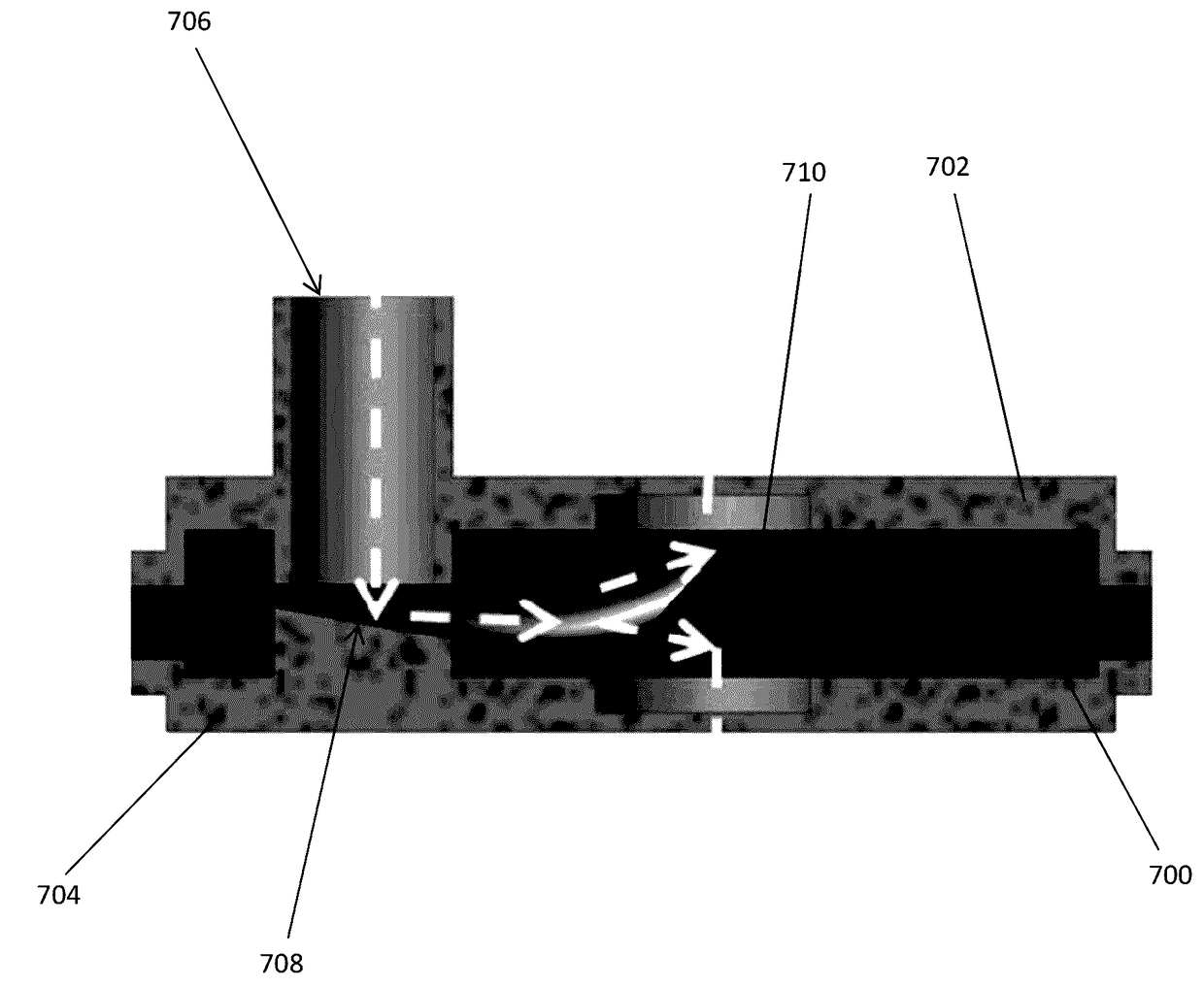
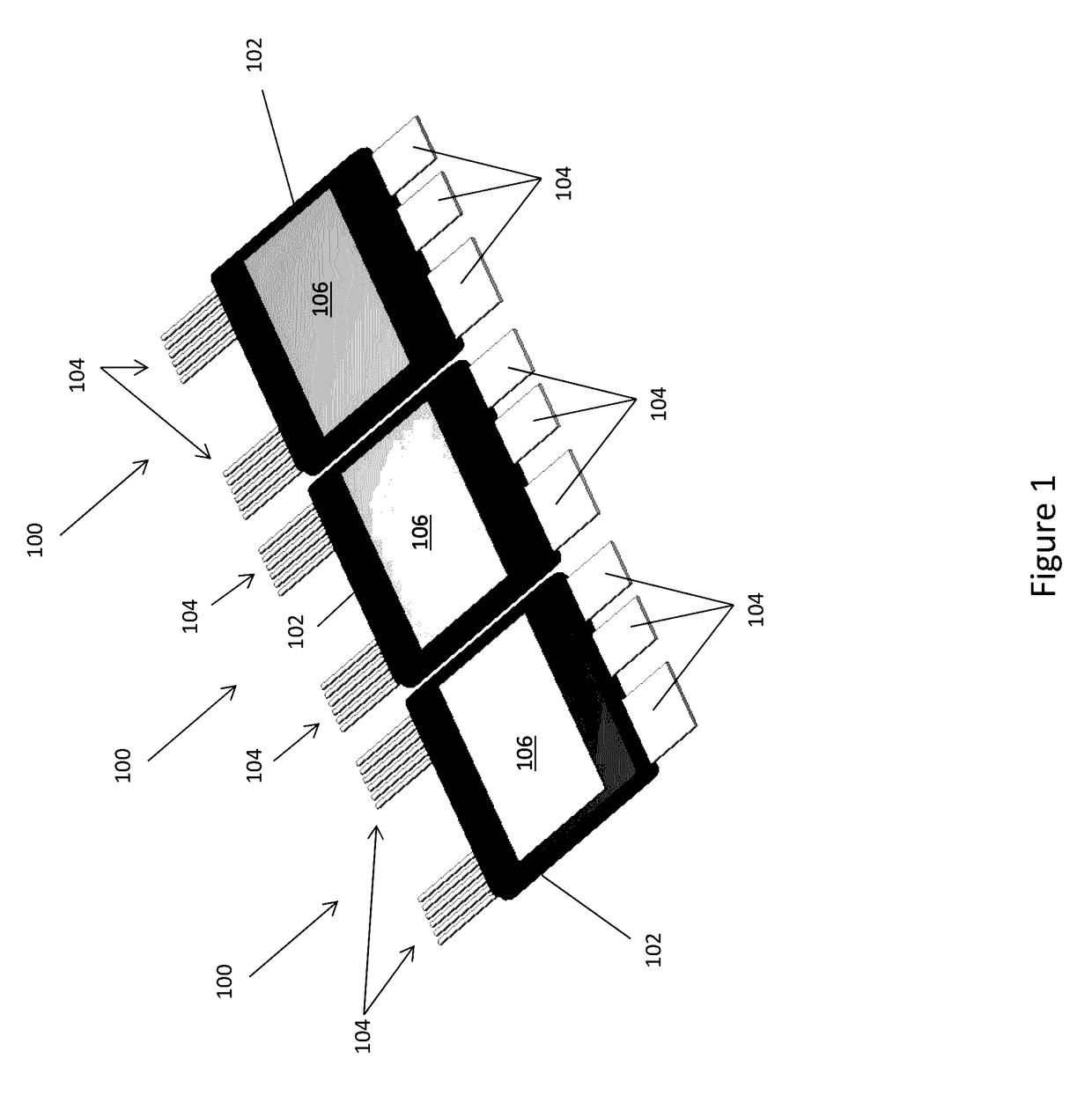
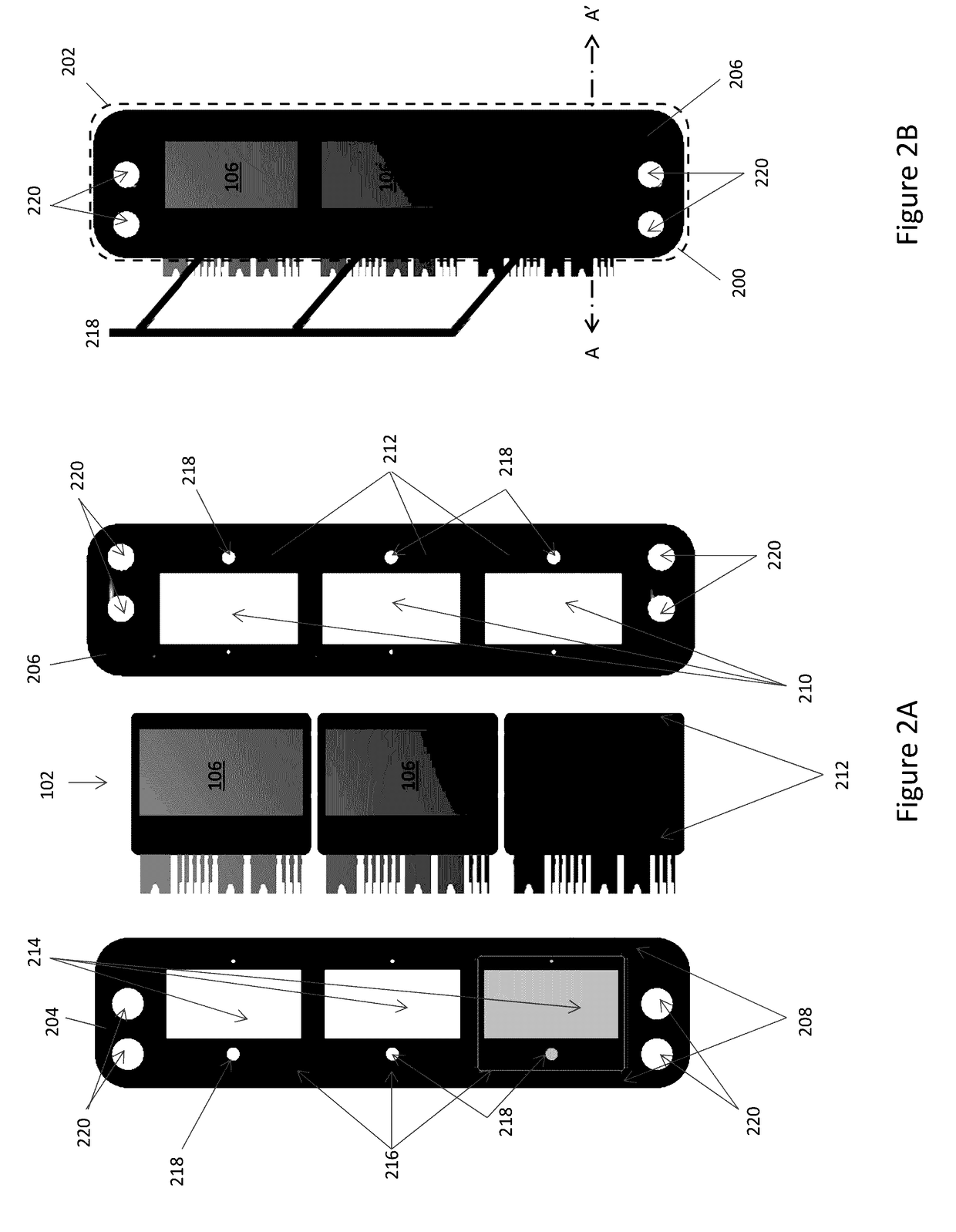
[0018]According to embodiments described herein, a cooling system for molded semiconductor modules is provided. Each semiconductor module includes a semiconductor die encapsulated by a mold compound, a plurality of leads electrically connected to the semiconductor die and at least partly uncovered by the mold compound, and a first cooling plate at least partly uncovered by the mold compound. The cooling system further comprises a plastic housing which surrounds the periphery of each module to form a multi-die module, The plastic housing includes a first singular plastic part which receives the modules and a second singular plastic part attached to a periphery of the first plastic part. The second plastic part has cutouts which expose the first cooling plates and a sealing structure containing a sealing material which forms a water-tight seal around the periphery of each module at a side of the modules with the first cooling plates.

[0019]In the case of double-sided cooling, each disc...


PUM


Abstract

A cooling apparatus is manufactured by: receiving a discrete module by a first singular part, the discrete module including a semiconductor die encapsulated by a mold compound, a plurality of leads electrically connected to the semiconductor die and protruding out of the mold compound, and a first cooling plate at least partly uncovered by the mold compound; attaching a second singular part to a periphery of the first part to form a housing, the housing surrounding a periphery of the discrete module, the second part having a cutout which exposes the first cooling plate and a sealing structure facing a side of the discrete module with the first cooling plate; and filling the sealing structure with a sealing material which forms a water-tight seal around the periphery of the discrete module at the side of the discrete module with the first cooling plate.

Description

TECHNICAL FIELD[0001]The instant application relates to semiconductor modules, and more particularly to cooling systems for semiconductor modules.BACKGROUND[0002]Power modules with double-side cooling significantly improve the thermal performance of the package by reducing thermal resistance, and thereby increasing the power density of the entire system. However, power modules with double-sided cooling present a challenge with regard to integrating a heat-sink with the module. The design of the cooler often is a critical issue in achieving the highest possible performance. For example, the cooling fluid should be distributed in two different channels above and below the power modules included in the package to increase the thermal performance of the package. Also, the entire system must be watertight. The heat sink should be robust, low-cost and lightweight.[0003]Conventional double-sided module cooling technologies require additional parts such as O-rings and bolts or screws to ach...

Claims


Application Information

Patent Timeline
IPC IPC(8): H01L21/48H01L23/367H01L23/31H01L21/54H01L23/473H01L23/08H01L21/56
CPCH01L21/4882H01L23/08H01L23/3672H01L21/565H01L23/3142H01L21/4817H01L23/473H01L21/4875H01L21/54H01L23/18H01L23/3107H01L23/3737H01L23/44H01L23/49811
Inventor YOO, INPILGRASSMANN, ANDREAS
Owner INFINEON TECH AG
Learn More