
Degassing liquid eluent of a preparative sfc fluid chromatography system

a fluid chromatography and liquid eluent technology, applied in the field of degasser, can solve the problems of interference with subsequent flow and downstream process, collection and detection, and achieve the effects of minimizing the added volume of the system, reducing the splatter in the collection vessel, and minimizing the outgassing

Inactive Publication Date: 2017-05-18
WATERS TECH CORP
View PDF2 Cites 3 Cited by
  • Summary
  • Abstract
  • Description
  • Claims
  • Application Information

AI Technical Summary

Benefits of technology

This patent describes a new apparatus, system, and method for removing dissolved gas from a supersaturated solution. The apparatus is made of gas-permeable material that is placed after a chromatography column and before a fraction collector or detector. The apparatus reduces outgassing, minimizes splatter in collection vessels, and improves detection of peaks. Overall, this technology ensures a more consistent flow of the solution and efficient collection of the separated materials.

Problems solved by technology

High amounts of remaining dissolved gas can lead to outgassing (i.e., aerosolization) and interfere with subsequent flow and downstream processes, such as fraction collection and detection.

Method used


Image

  • Degassing liquid eluent of a preparative sfc fluid chromatography system
  • Degassing liquid eluent of a preparative sfc fluid chromatography system
  • Degassing liquid eluent of a preparative sfc fluid chromatography system

Examples


example 1

Including Amorphous Fluoroplastic Polymer Tubing

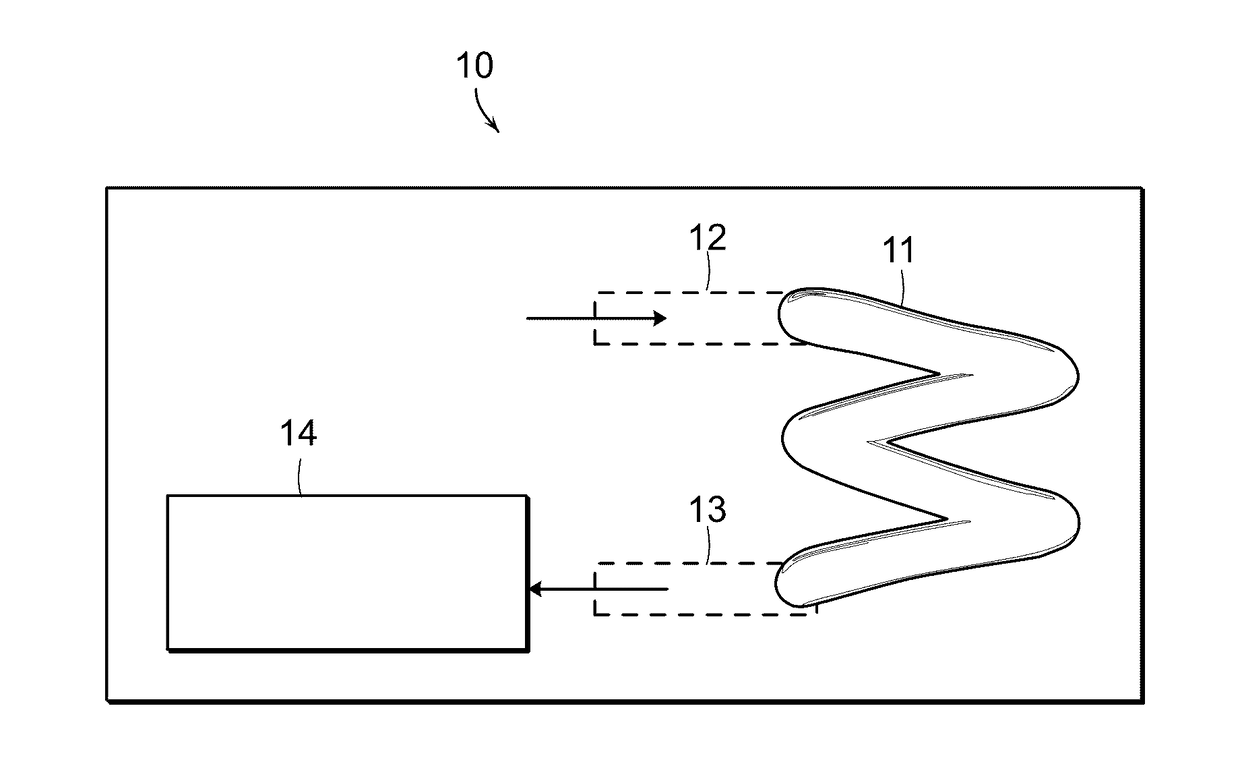
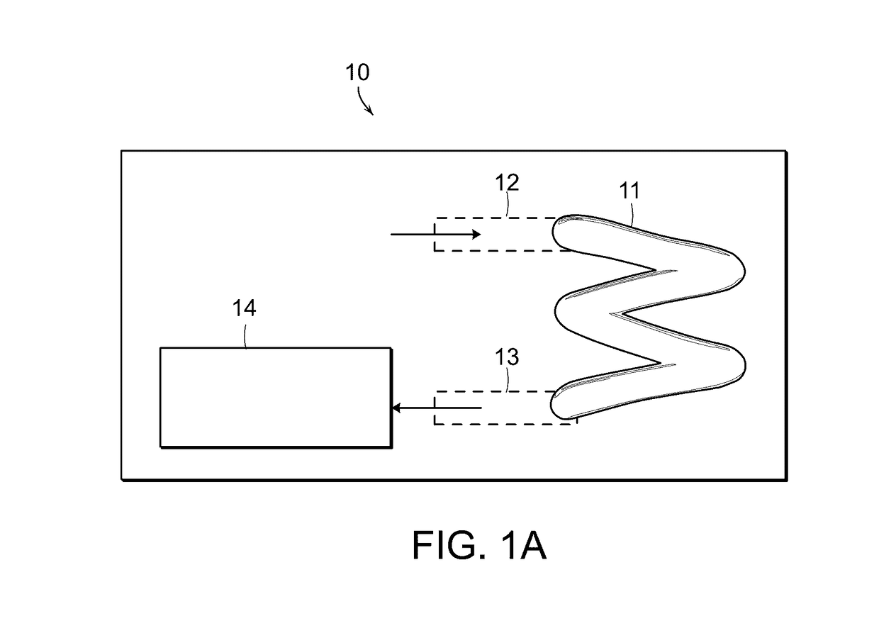
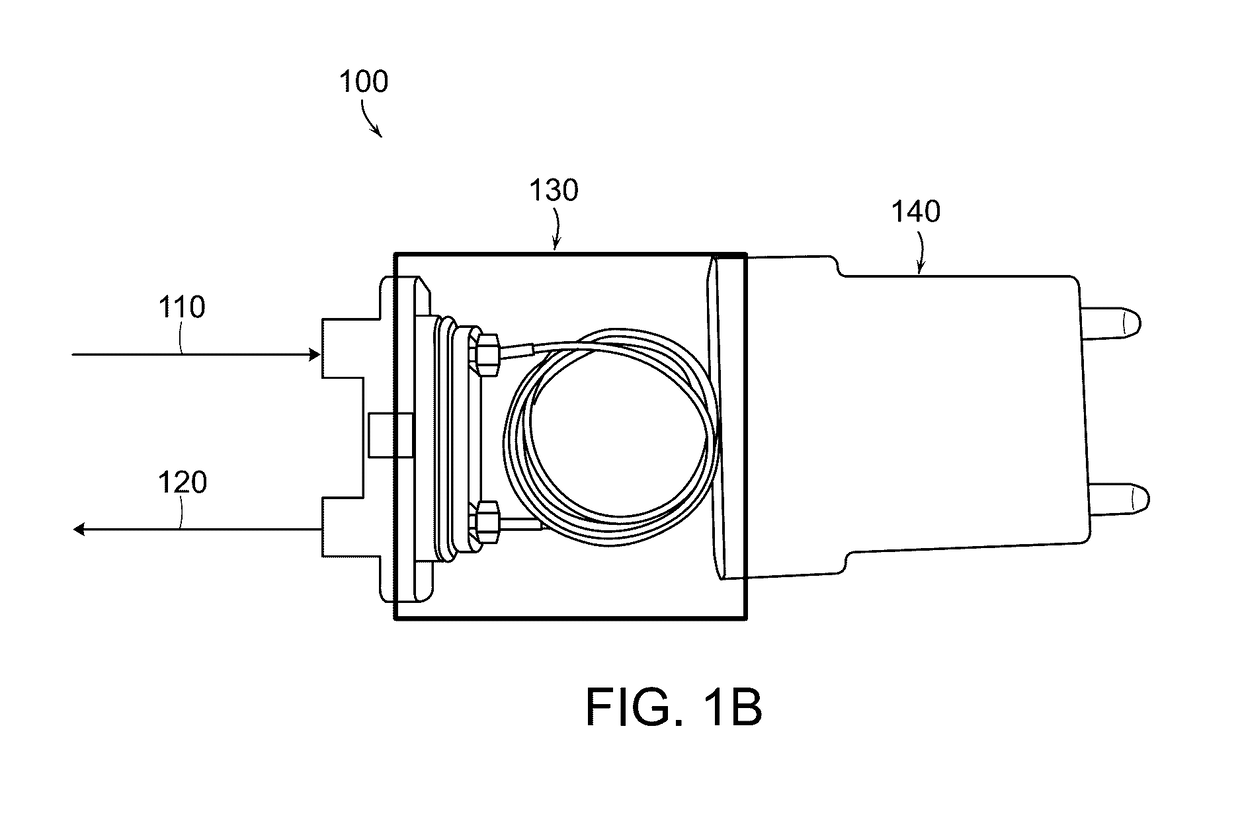
[0100]A supersaturated solution in a mixed fluid system is degassed using a degasser including a continuous body of gas-permeable tubing formed at least in part from an amorphous fluoroplastic polymer, such as but not limited to the TEFLON® AF amorphous fluoroplastic (a fluorinated ethylenic-cyclooxyaliphatic substituted ethylenic copolymer available from DuPont, Wilmington, Del.). The mixed fluid system includes, such as the system shown in FIG. 7, a mixer 710, a gas-liquid separator 720, a degasser 730 and at least one of a fraction collector 740 or a detector 750. The supersaturated solution includes a mixture of 95% carbon dioxide and 5% methanol by volume, at room temperature and 1 bar. The supersaturated solution is degassed in the degasser 730 after separation in the gas liquid separator. The degasser 730 in this example is formed of a continuous body of gas-permeable amorphous fluoroplastic polymer tubing, such as that shown in...

example 2

Including Entangled (or Knitted) Amorphous Fluoroplastic Polymer Tubing

[0101]A supersaturated solution in a mixed fluid system is degassed using a degasser including a continuous body of entangled gas-permeable tubing formed at least in part from an amorphous fluoroplastic polymer, such as but not limited to the TEFLON® AF amorphous fluoroplastic (a fluorinated ethylenic-cyclooxyaliphatic substituted ethylenic copolymer commercially available from Dupont, Wilmington, Del.). The mixed fluid system includes, such as the system shown in FIG. 7, a mixer 710, a gas-liquid separator 720, a degasser 730 and at least one of a fraction collector 740 or a detector 750. The supersaturated solution includes a mixture of 95% carbon dioxide and 5% methanol by volume, at room temperature and 1 bar. The supersaturated solution is degassed in the degasser 730 after separation in the gas liquid separator. The degasser 730 in this example is formed of a continuous body of entangled gas-permeable amorp...


PUM

PropertyMeasurementUnit
lengthaaaaaaaaaa
lengthaaaaaaaaaa
lengthaaaaaaaaaa

Abstract

Methods, systems and apparatus are provided for degassing a supersaturated solution. An example degasser is described having a continuous body of gas-permeable tubing to remove an amount of a gas from the supersaturated solution below the gas's saturation point in the supersaturated solution. The degasser can be connected to at least one of a fraction collector or a detector. The example degasser is sized and / or positioned to cause a change in pressure (ΔP) across the degasser to drive removal of a dissolved gas from a supersaturated solution passing through the degasser. As a result of the reduction of gas, efficiencies in system flow and fraction collection are achieved.

Description

RELATED APPLICATION[0001]This application claims the benefit of and priority to U.S. Provisional Application No. 62 / 246,326 filed Oct. 26, 2015 and entitled “Degassing Liquid Eluent of a Preparative SFC Fluid Chromatography System,” which is owned by the assignee of the instant application and the disclosure of which is hereby incorporated by reference in its entirety.TECHNICAL FIELD[0002]The present technology relates to a degasser for removing gas from a supersaturated solution. In particular, the present disclosure relates to methodologies, systems and apparatus for degassing a supersaturated solution within a degasser having gas-permeable tubing. The degasser can be used in carbon dioxide based chromatography preparative or analytical systems.BACKGROUND OF THE TECHNOLOGY[0003]In general, chromatography involves the flowing of a mobile phase over a stationary phase to effect separation. To speed-up and enhance the efficiency of the separation, pressurized mobile phases were intro...

Claims


Application Information

Patent Timeline
Patent Type & Authority Applications(United States)
IPC IPC(8): B01D19/00G01N30/14B01D15/40
CPCB01D19/0073G01N30/14B01D15/40B01D19/0031G01N30/84G01N2030/8423
Inventor JACKSON, MICHAEL R.SEITH, CHRISTOPHERBALA, SENTHILFREDETTE, COLINSOK, MARUTHGOMEZ, CARLOSSHREVE, JOSHUA A.
Owner WATERS TECH CORP
Learn More