Eureka AIR delivers breakthrough ideas for toughest innovation challenges, trusted by R&D personnel around the world.

Method for operating a spindle of a two-for-one twisting or cabling machine

a two-for-one twisting or cabling machine technology, applied in the direction of yarn, continuous wounding machines, textiles and papermaking, etc., can solve the problems of increasing energy requirements, inability or respectively extremely difficult to vary the height of the yarn balloon during the operation of the workstation, and relatively long physical contact of the circulating yarn balloon with the stationary balloon limiter, so as to achieve the effect of free view of the circulating yarn balloon

Active Publication Date: 2017-05-11
SAURER TECH GMBH & CO KG
View PDF18 Cites 9 Cited by
  • Summary
  • Abstract
  • Description
  • Claims
  • Application Information

AI Technical Summary

Benefits of technology

The invention is a method that allows a spindle of a two-for-one twisting or cabling machine to operate safely and efficiently with an adjustable balloon-yarn-guide-eye. The technical effect is to improve the production process and reduce the energy consumption of the machine.

Problems solved by technology

In the case of the workstations of the known two-for-one twisting or cabling machines, in which the height of the circulating yarn balloon is limited in each case by a balloon-yarn-guide or respectively a balloon-yarn-guide-eye, it is often not possible or respectively extremely difficult to vary the height of the yarn balloon during the operation of the workstation.
However, since large yarn balloons are known to lead to relatively large ventilation losses and therefore to an increased energy requirement of the workstations of the two-for-one twisting or cabling machines, various attempts have already been made in the past, especially in conjunction with less friction-sensitive yarn materials, such as cotton, to reduce or respectively to limit the diameter of the yarn balloons.
However, the disadvantage with these known two-for-one yarn-twisting spindles is the relatively long physical contact of the circulating yarn balloon with the stationary balloon limiter.
However, no indications can be derived from European Patent Publication EP 2 260 132 B1 regarding the constructive constitution of the vertically adjustable yarn balloon guide.
With such an arrangement, all of the balloon-yarn-guides on one side of the machine are displaced together during the spinning operation; a separate control of the balloon-yarn-guide of an individual workstation is not possible.

Method used


Image

  • Method for operating a spindle of a two-for-one twisting or cabling machine
  • Method for operating a spindle of a two-for-one twisting or cabling machine
  • Method for operating a spindle of a two-for-one twisting or cabling machine

Examples


Embodiment Construction

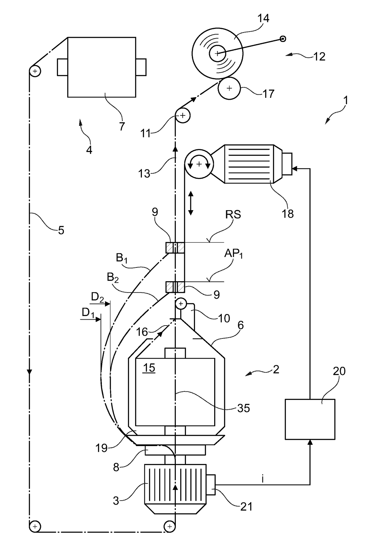
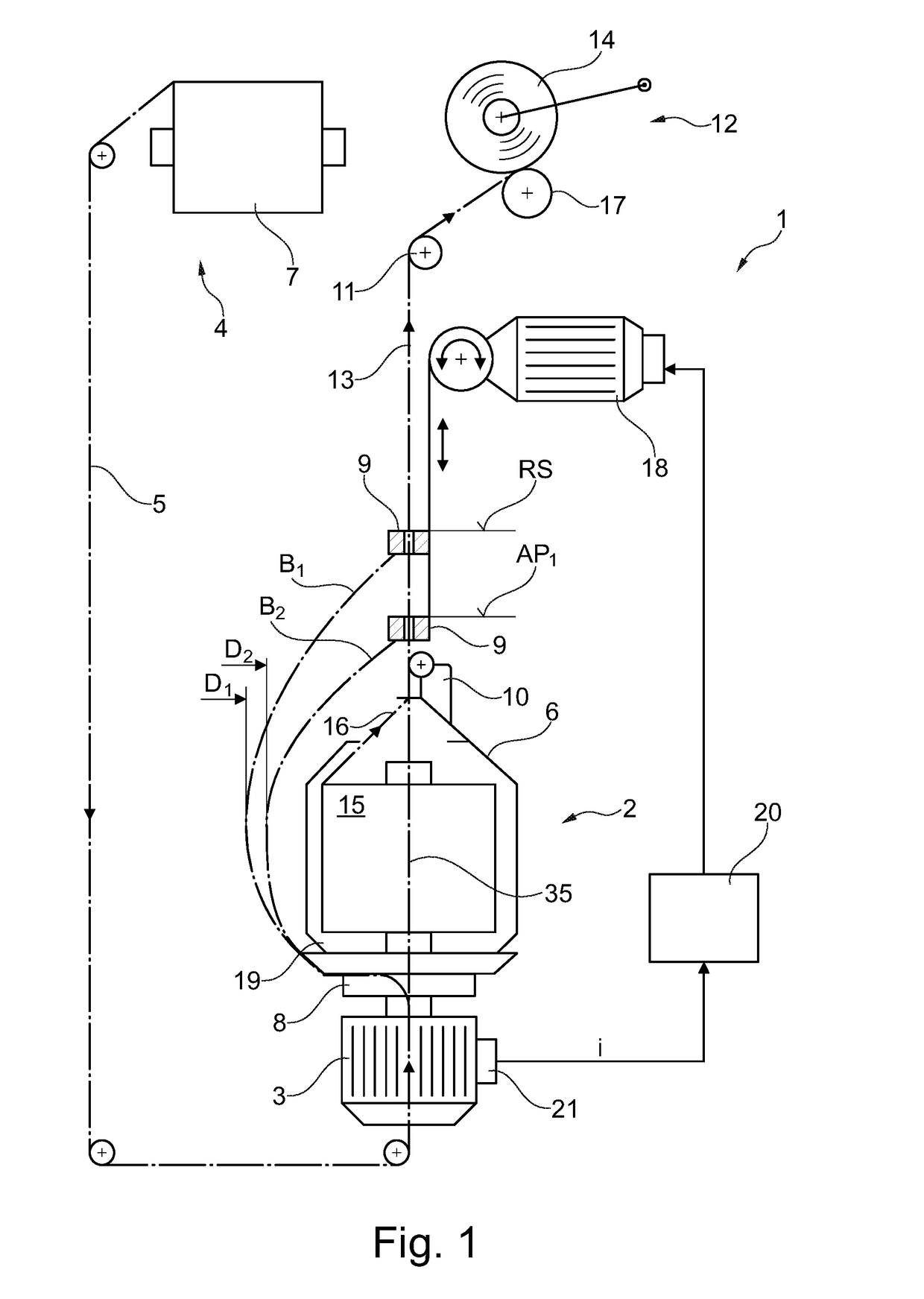
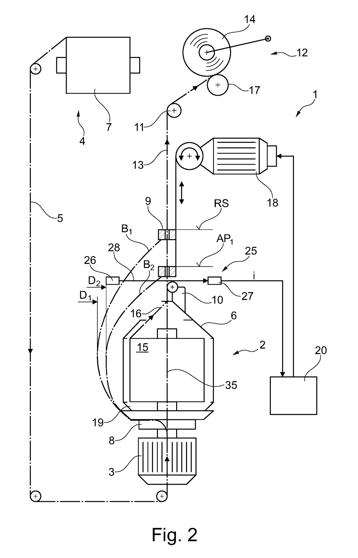
[0067]FIG. 1 shows a schematic lateral view of a workstation 1 of a two-for-one twisting or cabling machine.

[0068]In the exemplary embodiment, the workstation 1 is fitted with a spindle 2 constituted as a cabling spindle.

[0069]The workstation 1 comprises a balloon-yarn-guide-eye 9, which is height adjustable by means of an adjustment drive 18 and can be optionally positioned in a starting position designated as resting position RS or a first operating position AP1.

[0070]In this context, the adjustment drive 18 is connected to a control circuit 20, which is further connected to a device 21 for generating a measured value i.

[0071]Above or behind the workstation 1, a bobbin rack 4 (not illustrated in greater detail) is positioned, which generally serves to accommodate several feed bobbins 7.

[0072]From one of these feed bobbins 7, referred to in the following as the first feed bobbin 7, a so-called outer yarn 5 is withdrawn, which, deflected several times in the region of a rotational a...


PUM


Abstract

A method for operating a spindle (2) of a two-for-one twisting or cabling machine which comprises an adjustable balloon-yarn-guide-eye (9), wherein for the operation of the spindle (2) under production conditions, the balloon-yarn-guide-eye (9) is adjusted, on the basis of a measured value (i) correlating with the energy consumption of the spindle drive (3), to a first operating position (AP1), in which a position-dependent minimum of the energy consumption of the spindle drive (3) is reached.

Description

CROSS-REFERENCE TO RELATED APPLICATIONS[0001]This application claims priority from German National Patent Application No. DE 10 2015 014 383.2, filed Nov. 9, 2015, entitled “Verfahren zum Betreiben einer Spindel einer Doppeldrahtzwirn-oder Kabliermaschine”, the entire contents of which are incorporated herein by reference.FIELD OF THE INVENTION[0002]The present invention relates to a method for operating a spindle of a two-for-one twisting or cabling machine which comprises an adjustable balloon-yarn-guide-eye.BACKGROUND OF THE INVENTION[0003]Since a single yarn often cannot satisfy the requirements which are placed on it with regard to its strength and / or its uniformity during further processing or in the finished product, it is conventional in the textile industry for at least two yarns to be twisted together, for example, by means of a two-for-one twisting or cabling machine, wherein, however, in principle, the winding up of individual yarns is also possible in the two-for-one tw...

Claims


Application Information

Patent Timeline
IPC IPC(8): D01H7/86D01H1/10D01H1/16D01H1/244D01H9/18
CPCD01H7/86D01H1/244D01H1/103D01H1/166D01H9/18D01H1/10D01H13/26D02G3/28D01H1/106D01H7/868D02G3/285D07B2207/4009
Inventor RAISICH, ANDREJSCHNITZLER, JURGEN
Owner SAURER TECH GMBH & CO KG
Why Eureka
Eureka Blog
Learn More