
Hydrogen generation electrode and artificial photosynthesis module

a technology of photosynthesis module and hydrogen generation electrode, which is applied in the direction of electrode coating, oxygen/ozone/oxide/hydroxide, multiple component coating, etc., can solve the problems of destructing the photoelectric conversion part and reducing the durability

Active Publication Date: 2017-05-11
FUJIFILM CORP +2
View PDF0 Cites 5 Cited by
  • Summary
  • Abstract
  • Description
  • Claims
  • Application Information

AI Technical Summary

Benefits of technology

The patent text describes the results of an experiment where different hydrogen generation electrodes were made. The technical effects of this invention are not explicitly stated, but it seems to confirm the effectiveness of the invention in producing hydrogen using these specific electrodes.

Problems solved by technology

However, if the photoelectric conversion part having the first electrode for electrolysis and the pn junction is immersed in the electrolytic aqueous solution and driven for a long time, there is a problem that bubbles are formed inside the photoelectric conversion part, the photoelectric conversion part is destructed because the bubbles grow large, and durability degrades.

Method used


Image

  • Hydrogen generation electrode and artificial photosynthesis module
  • Hydrogen generation electrode and artificial photosynthesis module
  • Hydrogen generation electrode and artificial photosynthesis module

Examples


example 1

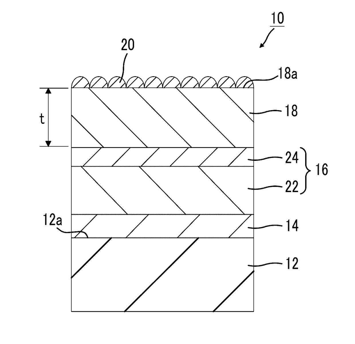
[0142]A hydrogen generation electrode of Example 1 has the same configuration as the hydrogen generation electrode 10 illustrated in FIG. 1. The configurations of respective parts are as follows. In the hydrogen generation electrode of Example 1, an exposed portion was covered with epoxy resin and insulated after a conducting wire was connected to a conductive layer.

[0143]

[0144]Insulating substrate: Soda lime glass, 1 mm in thickness

[0145]Conductive layer: Mo, 500 nm in thickness

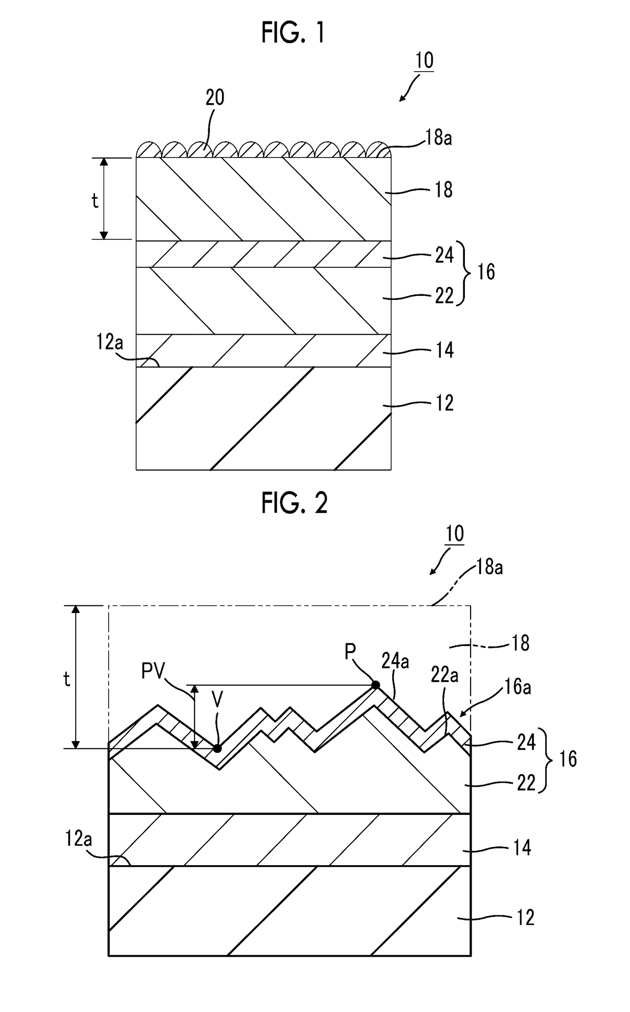
[0146]Inorganic semiconductor layer (peak-valley value (PV): 470 nm)

[0147]p-type semiconductor layer: CIGS, 1500 nm in thickness

[0148]n-type semiconductor layer: CdS, 50 nm in thickness

[0149]Functional layer: amorphous ITO, 600 nm in thickness

[0150](Steam permeability: 1.2 g / (m2·day))

[0151]Co-catalyst: Pt

[0152]In addition, as for the peak-valley value, after the formation of the hydrogen generation electrode, a portion of the hydrogen generation electrode was cut, and a sectional scanning electron microscope...

example 2

[0168](Making of Oxygen Generation Electrode)

[0169]A solution in which 1.0 g of nitric acid bismuth pentahydrate and 3.0 g of sodium iodide were dissolved with 50 ml of nitric acid with pH 1.7 was prepared. This solution was mixed with a solution in which 0.5 g of 1,4-benzoquinone was dissolved in 20 ml of ethanol, and ultrasonic waves were applied to dissolve the obtained solution. The obtained solution was put into a container for electrodeposition (a three-electrode system cell), a working electrode was set in a substrate with a transparent electrode, Ag / AgCl (4M KCl) was set in a reference electrode, and a platinum wire was set in a counter electrode. Electrodeposition was performed for 10 minutes on the working electrode and the reference electrode while maintaining a potential range of −0.1 V to −0.3 V. A BiOI thin film electrode was obtained by drying the electrodeposited electrodes.

[0170]Next, after the BiOI thin film electrode was immersed in a dimethyl sulfoxide solution (...


PUM

PropertyMeasurementUnit
thicknessaaaaaaaaaa
thicknessaaaaaaaaaa
thicknessaaaaaaaaaa

Abstract

A hydrogen generation electrode is used for an artificial photosynthesis module that decomposes an electrolytic aqueous solution into hydrogen and oxygen with light. The hydrogen generation electrode has a conductive layer, an inorganic semiconductor layer that is provided on the conductive layer and has a pn junction, and a functional layer that covers an inorganic semiconductor layer. The steam permeability of the functional layer is 5 g / (m2·day) or less.

Description

CROSS-REFERENCE TO RELATED APPLICATIONS[0001]This application is a Continuation of PCT International Application No. PCT / JP2015 / 070140 filed on Jul. 14, 2015, which claims priority under 35 U.S.C. §119(a) to Japanese Patent Application No. 2014-163668 filed on Aug. 11, 2014 and Japanese Patent Application No. 2015-069478 filed on Mar. 30, 2015. Each of the above application(s) is hereby expressly incorporated by reference, in its entirety, into the present application.BACKGROUND OF THE INVENTION[0002]1. Field of the Invention[0003]The present invention relates to a hydrogen generation electrode used for an artificial photosynthesis module that decomposes an electrolytic aqueous solution into hydrogen and oxygen by light, and an artificial photosynthesis module including this hydrogen generation electrode.[0004]2. Description of the Related Art[0005]In the related art, as one of the forms in which solar light energy that is renewable energy is utilized, devices that use a photoelectr...

Claims


Application Information

Patent Timeline
Patent Type & Authority Applications(United States)
IPC IPC(8): C25B11/04C25B1/00H01G9/20C25B9/06B01J35/00C25B9/17
CPCC25B11/0405C25B9/06H01G9/2045C25B1/003C25B11/0478C25B11/02C01B13/0207Y02E60/36C25B1/55C25B9/17C25B11/051C25B11/093C25B11/091
Inventor SATO, NAOTOSHIDOMEN, KAZUNARI
Owner FUJIFILM CORP
Learn More