
Data center management via out-of-band, low-pin count, external access to local motherboard monitoring and control

Active Publication Date: 2017-04-27
VAPOR IO INC
View PDF1 Cites 38 Cited by
  • Summary
  • Abstract
  • Description
  • Claims
  • Application Information

AI Technical Summary

Benefits of technology

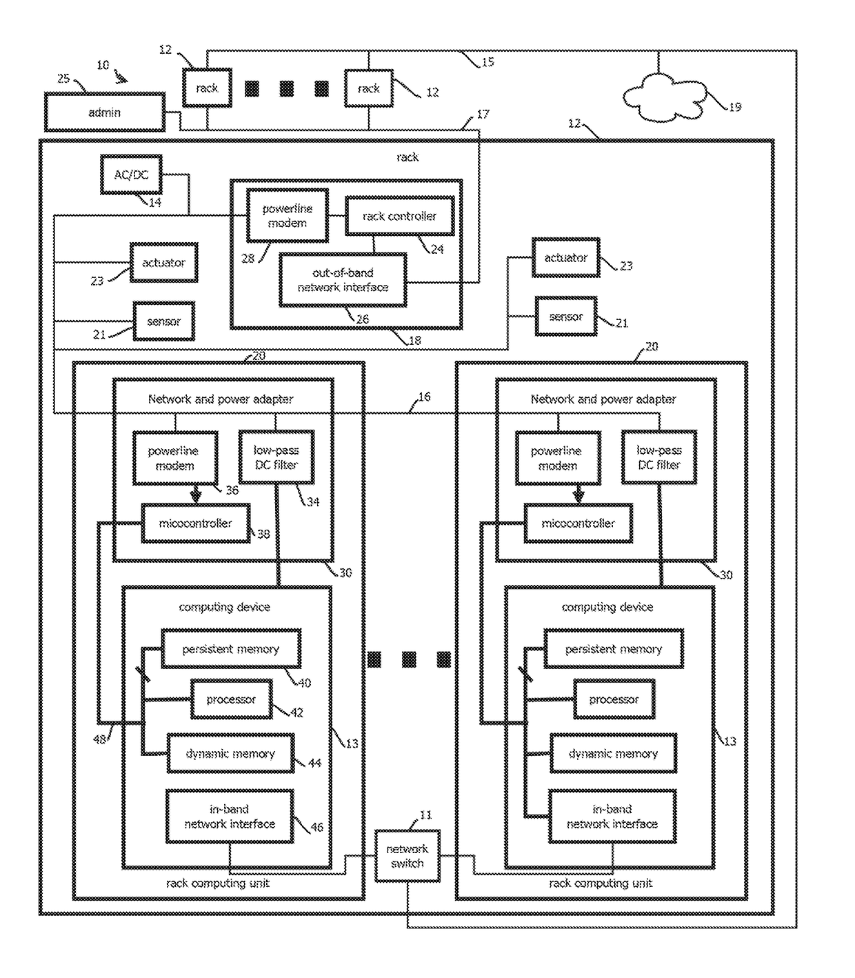
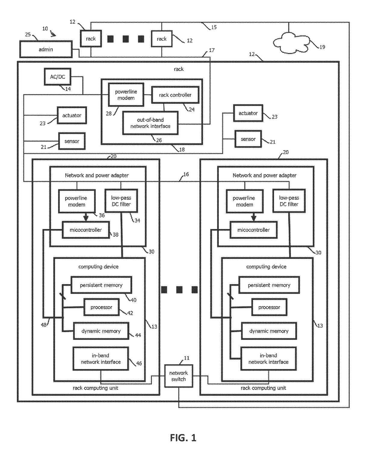
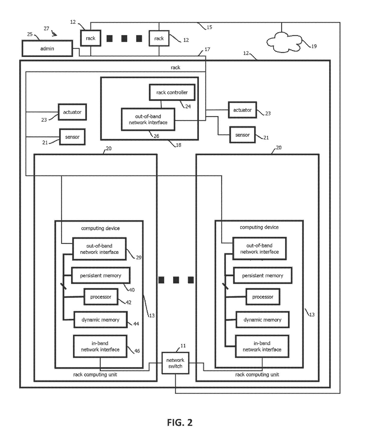
The patent describes a way to monitor and control a group of computers that are mounted in a rack. This is done through a secondary device that connects to the motherboard of the computers using a low-speed network. The secondary device receives instructions from a control device and sends them to the motherboard through the network. The motherboard then responds to these instructions and sends data back to the control device through the network. This allows for seamless monitoring and control of multiple computers in a rack.

Problems solved by technology

Traditional BMC implementations present a number of issues.
In many cases, BMC passwords are not secured, are difficult to manage, and are shared by a relatively large number of computing devices in a data center.
Further, once compromised, an on-board BMC can be difficult to remove, e.g., in some cases requiring a chip be desoldered or that the host system be discarded.

Method used


Image

  • Data center management via out-of-band, low-pin count, external access to local motherboard monitoring and control
  • Data center management via out-of-band, low-pin count, external access to local motherboard monitoring and control
  • Data center management via out-of-band, low-pin count, external access to local motherboard monitoring and control

Examples


embodiment 1

2. The secondary computing device of embodiment 1, wherein: the low-bandwidth bus is an System Management Bus (SMBus) connector that is a removable connector configured: to be held in place on the motherboard, at least in part, by a resilient member; and to connect to the SMBus via electrical contact with five or fewer conductors, a first conductor of the five or fewer conductors being a clock-signal conductor, a second conductor of the five or fewer conductors being a data conductor, the clock-signal conductor being configured to receive a clock-signal operating at less than 10 MHz.

3. The secondary computing device of any one of embodiments 1-2, comprising: the off-motherboard network interface communicatively coupled to the one or more processors.

embodiment 3

4. The secondary computing device of embodiment 3, wherein: the off-motherboard network interface comprises an Ethernet network interface.

5. The secondary computing device of embodiment 3, wherein: the off-motherboard network interface comprises a powerline communication modem.

embodiment 5

6. The secondary computing device of embodiment 5, comprising: a bus-bar connector configured to couple to a bus bar extending past, and providing direct current power to, a plurality of rack-mounted computing devices; and a filter configured to separate a data signal from direct current power conducted by the bus bar.

7. The secondary computing device of any one of embodiments 1-6, wherein the operations comprise: adjusting a fan speed of a fan controlled via the motherboard.

8. The secondary computing device of any one of embodiments 1-7, wherein the operations comprise: reading a value from a motherboard temperature sensor indicative of a temperature of a component on the motherboard.

9. The secondary computing device of any one of embodiments 1-8, wherein the operations comprise: reading a value from a motherboard voltage sensor indicative of a voltage of a conductive trace of the motherboard.

10. The secondary computing device of any one of embodiments 1-9, wherein the operations c...


PUM


Abstract

Provided is an external secondary computing device configured to monitor or control a rack-mounted computing device independently of whether the rack-mounted computing device is operating or is turned off via a low-pin-count motherboard bus independently of a baseboard management controller.

Description

CROSS-REFERENCE TO RELATED APPLICATIONS[0001]The present application is a continuation-in-part of U.S. patent application Ser. No. 15 / 366,528, titled DATA CENTER MANAGEMENT, filed 1 Dec. 2016, which is a continuation-in-part of U.S. patent application Ser. No. 15 / 065,212, titled OUT-OF-BAND DATA CENTER MANAGEMENT VIA POWER BUS, filed 9 Mar. 2016, which claims the benefit of the following U.S. Provisional patent applications: U.S. 62 / 130,018, titled RACK FOR COMPUTING EQUIPMENT, filed 9 Mar. 2015; U.S. 62 / 248,788, titled RACK FOR COMPUTING EQUIPMENT, filed 30 Oct. 2015; and U.S. 62 / 275,909, titled RACK FOR COMPUTING EQUIPMENT, filed 7 Jan. 2016. The entire content of each parent application is incorporated by reference in its entirety.BACKGROUND[0002]1. Field[0003]The present invention relates generally to computing equipment and, more specifically, to secondary computing devices to monitor and control primary computing devices for data centers.[0004]2. Description of the Related Art...

Claims


Application Information

Patent Timeline
IPC IPC(8): G06F11/30G06F13/40
CPCG06F11/3055G06F11/3048G06F11/3051G06F11/3027G06F13/4068H04L41/24G06F1/189G06F1/206G06F1/26H04L67/1042H04L41/344
Inventor CENCINI, ANDREW BRIANWHITE, STEVENCRAWFORD, COLTON MALONE
Owner VAPOR IO INC
Learn More