
Insert and tool holder for mounting same

a technology for inserts and tool holders, applied in the field of inserts, can solve the problems of difficult fabrication of tool holders, deterioration of coupling characteristics, and increase the thickness of inserts, so as to reduce the length of main cutting edges, increase cutting depth, and improve the effect of machinability

Active Publication Date: 2017-04-27
KORLOY
View PDF24 Cites 5 Cited by
  • Summary
  • Abstract
  • Description
  • Claims
  • Application Information

AI Technical Summary

Benefits of technology

The present invention provides various technical configurations for the insert and tool holder, which improve machinability and minimize interference between the tool holder and the workpiece. These technical configurations include an inclination angle of the main cutting edge, different clearance angles for the main and sub sides surfaces, and a greater clearance angle for the second end main side surface with respect to the lower surface. These configurations allow for enhanced machinability without increasing the thickness or reducing the length of the cutting edge, and also minimize interference between the tool holder and the workpiece.

Problems solved by technology

In order to overcome such limit, the thickness of the insert can be increased, but in that case, it is difficult to fabricate a tool holder, and coupling characteristic also deteriorates.
If the main cutting edge is fabricated to be approximately half the size of one side surface, this rather causes deteriorated cutting efficiency because the cutting depth is decreased.

Method used


Image

  • Insert and tool holder for mounting same
  • Insert and tool holder for mounting same
  • Insert and tool holder for mounting same

Examples


Embodiment Construction

[0026]Certain exemplary embodiments of the present inventive concept will be described in greater detail with reference to the accompanying drawings to enable those skilled in the art to work the present disclosure. However, it is not intended to limit the technology described herein to any specific embodiments, as it should be construed as encompassing various modifications, equivalents and / or alternatives of the embodiments.

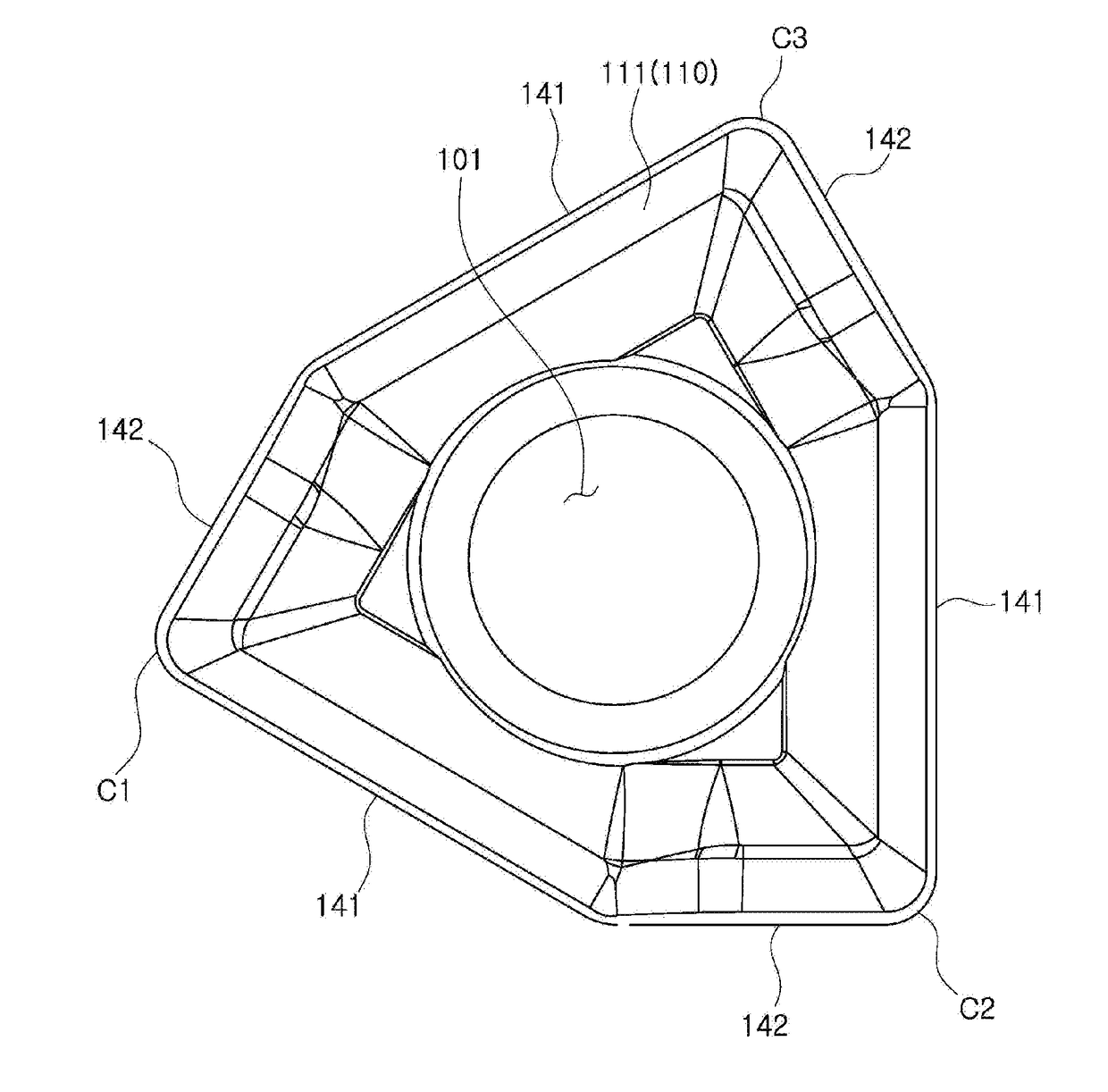
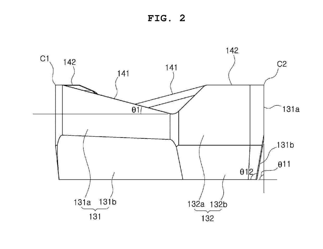
[0027]FIG. 1 is a perspective view illustrating an insert according to an embodiment of the present disclosure, FIG. 2 is a side view illustrating a main side surface and a sub side surface in parallel with each other, of the insert of FIG. 1, and FIG. 3 is a side view seen from a corner side, to show the first end main side surface and the sub side surface, and the second end main side surface altogether, of the insert of FIG. 1.

[0028]FIG. 4 is a plan view illustrating an upper surface of the insert of FIG. 1, and FIG. 5 is a bottom perspective view illustrati...


PUM

PropertyMeasurementUnit
perimeteraaaaaaaaaa
angleaaaaaaaaaa
heightaaaaaaaaaa

Abstract

An insert in which a cutting edge is formed only between an upper surface and a side surface. The insert comprises: three or more corners along a perimeter; a main cutting edge formed on an edge between an upper surface and a main side surface, and a sub cutting edge formed on an edge between the upper surface and a sub side surface, wherein the main cutting edge and the sub cutting edge are placed in succession between the corners; and a flat lower surface. The main cutting edge forms an inclination angle such that a height decreases gradually in a direction toward the sub cutting edge. The main side surface is formed by a first end main side surface and a second end main side surface. The sub side surface is formed by a first end sub side surface and a second end sub side surface.

Description

TECHNICAL FIELD[0001]The present disclosure relates to an insert for use in cutting or grooving, and a tool holder for mounting the same.BACKGROUND ART[0002]Generally, an insert is coupled to a cutting tool mounted on a machine tool, and used for cutting a workpiece composed of ferrous, nonferrous metal, nonmetal materials, and so on.[0003]Such insert typically includes an upper surface, a lower surface, and a plurality of side surfaces connecting the upper surface with the lower surface. An upper cutting edge is provided between the side surface and the upper surface, and a lower cutting edge is provided between the side surface and the lower surface.[0004]One of conventional examples is disclosed in Korean Pat. No. 10-1240880 and illustrated in FIGS. 7 and 8, which is a double sided insert including an upper side (upper surface) 11, a lower side (upper surface) 12, and cutting edges 13A, 13B, 14A, 14B, 15A, 15B formed therebetween, in which the upper side 11 and the lower side 12 ...

Claims


Application Information

Patent Timeline
Patent Type & Authority Applications(United States)
IPC IPC(8): B23C5/20B23C5/06
CPCB23C5/207B23C2210/168B23C2200/0411B23C5/06B23C2200/286B23C2200/125B23C2210/045B23C5/202B23C5/2213B23C5/205B23C5/20B23C5/22
Inventor NAM, KI-CHANLEE, KANE-HEEKIM, YOUNG-HEUM
Owner KORLOY
Learn More