
Objective, Real-Time Acoustic Measurement and Feedback for Proper Fit and Fill of Hip Implants

a hip implant and real-time acoustic measurement technology, applied in the field of objective real-time acoustic measurement and feedback for proper fit and filling of hip implants, can solve the problems of limiting the range of motion and weight bearing strength of a person, prone to technical errors in procedures, and significant pain

Inactive Publication Date: 2017-04-27
RGT UNIV OF CALIFORNIA
View PDF0 Cites 7 Cited by
  • Summary
  • Abstract
  • Description
  • Claims
  • Application Information

AI Technical Summary

Benefits of technology

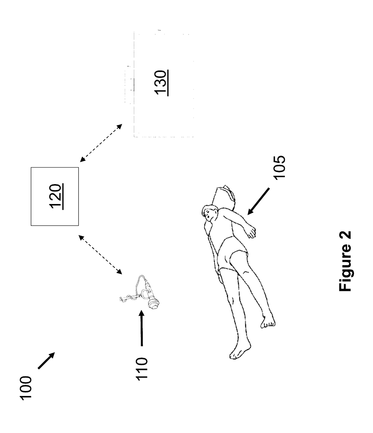
This patent describes a method to determine the position of an implant in bone by analyzing the sound created by hammering the implant into the bone. The hammering sequence creates a unique sound that is different for each position of the implant. The method involves collecting the audio signals, segmenting them, and classifying them based on the position of the implant. The system also includes a microphone, digital display, and control unit to provide feedback to the surgeon. This technology provides a non-invasive and efficient way to determine the fit of an implant in bone.

Problems solved by technology

Total hip replacement procedures seek to replace a hip joint that has deteriorated in its functionality, limiting a person's range of motion and weight bearing strength, in addition to causing significant pain.
While highly skilled, orthopedic surgeons currently are forced to rely solely on operative experience and manual assessment of the fit of implants in bone during an implant placement process, which inevitably leaves the procedure prone to technical error.
These errors can lead to pain and sometimes require revision surgery that can greatly increase the patient's risk of death and also add to the cost burden of healthcare.
Although surgeons currently use X-ray templates to estimate the placement of implants prior to surgery, these 2-dimensional preparations fail to fully account for the 3-dimensional aspects of surgery as well as the surgeon's training background.

Method used


Image

  • Objective, Real-Time Acoustic Measurement and Feedback for Proper Fit and Fill of Hip Implants
  • Objective, Real-Time Acoustic Measurement and Feedback for Proper Fit and Fill of Hip Implants
  • Objective, Real-Time Acoustic Measurement and Feedback for Proper Fit and Fill of Hip Implants

Examples


experimental examples

[0061]The invention is further described in detail by reference to the following experimental examples. These examples are provided for purposes of illustration only, and are not intended to be limiting unless otherwise specified. Thus, the invention should in no way be construed as being limited to the following examples, but rather, should be construed to encompass any and all variations which become evident as a result of the teaching provided herein.

example 1

[0062]A prototype was constructed comprising a microphone and computing system with display, running software and algorithms resulting in the following data:

Audio Processing

[0063]Audio data was separated into individual hammer hits, which were analyzed separately. Separation was performed by downsampling the signal by a factor of 100 samples per sample, smoothing an incoming signal using total variation reconstruction, and using a deadband threshold to detect the impact of the hammer in the audio.

Feature Extraction

[0064]Audio was transformed by applying a Hanning window to the signal, and then taking the discrete Fourier transform (DFT). Signal power in frequency bands of interest, time-domain decay of these components, and other features such as entropy were extracted for use as classifying features (FIG. 7). The signal power in the 1-2 kHz and 5-7 kHz bands in particular were indicative of whether a broach was fully seated in the femur. (FIG. 8)

Classification

[0065]Machine learning...


PUM


Abstract

The present invention relates to a system and method for objective, real-time acoustic measurement and feedback for proper fit and fill of hip implants during total hip replacement surgery, or other bone implant surgical procedures.

Description

CROSS-REFERENCE TO RELATED APPLICATIONS[0001]This application claims priority to U.S. Patent Application Ser. No. 62 / 007,332, filed Jun. 3, 2014, the entire contents of which are incorporated herein by reference.BACKGROUND OF THE INVENTION[0002]Total hip replacement procedures seek to replace a hip joint that has deteriorated in its functionality, limiting a person's range of motion and weight bearing strength, in addition to causing significant pain. Total hip replacement typically involves removal of the femoral head, neck, and a portion of the top of the femur in order to replace these structures with prosthetic components.[0003]Skeletal development and posture can be highly variable from person to person, while the prosthetic components are generally standardized. Thus, each hip replacement procedure is unique to the patient, and requires the surgeon to accommodate for these differences. A surgeon will typically measure both hip joints, including the neck-shaft angles, vertical ...

Claims


Application Information

Patent Timeline
Patent Type & Authority Applications(United States)
IPC IPC(8): A61F2/46
CPCA61F2/4607A61F2002/4681A61F2002/4671A61F2/4657A61B5/7267A61B7/005A61B9/00
Inventor GUNN, CAMERON ALLANHAFZALLA, GEORGE WAGDIBENGS, BENJAMIN CHRISTOPHER
Owner RGT UNIV OF CALIFORNIA
Learn More