
Method, Device and User Terminal for Measuring Discovery Signal

a discovery signal and user terminal technology, applied in the field of communication technology, can solve the problems of significant fluctuations in load and interference of small cell systems, and achieve the effect of reducing measurement deviation and increasing rsrq measurement accuracy

Active Publication Date: 2017-04-20
ZTE CORP
View PDF6 Cites 9 Cited by
  • Summary
  • Abstract
  • Description
  • Claims
  • Application Information

AI Technical Summary

Benefits of technology

The present patent aims to improve the accuracy of RSSI measurement by performing the measurement based on a sub-frame where a discovery signal is located or a sub-frame without a discovery signal. This helps to reduce the deviation in measurement caused by no data in a data channel after a cell is closed.

Problems solved by technology

In addition, with the movement of the User Equipment (UE), the UE would constantly move in or move out of the small cell, and the load and interference of the Small Cell system would show significant fluctuations.

Method used


Image

  • Method, Device and User Terminal for Measuring Discovery Signal
  • Method, Device and User Terminal for Measuring Discovery Signal

Examples


Embodiment Construction

[0030]The present document is further illustrated in details in conjunction with the accompanying drawings and the embodiments below. It should be understood that the specific embodiments described herein are only used for explaining the present document and are not intended to limit the present document.

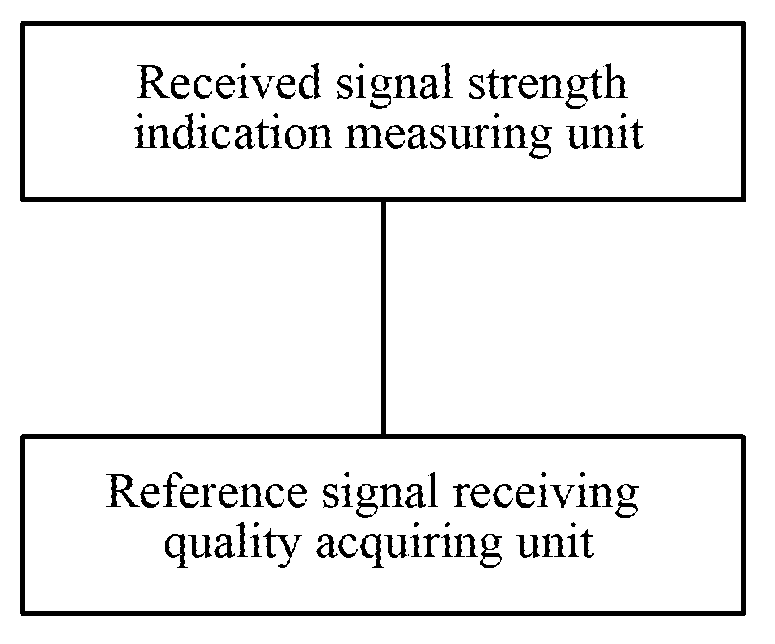
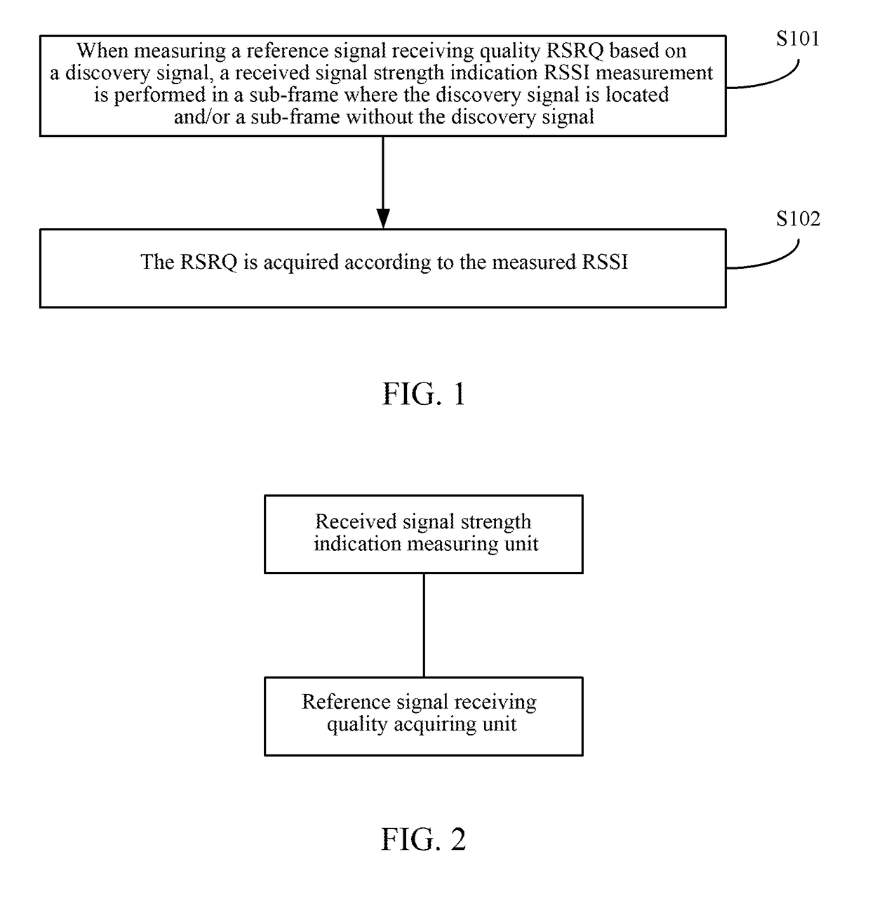
[0031]As shown in FIG. 1, the embodiment of the present document involves a method for measuring with a discovery signal, including the following steps.

[0032]In step S101, when an RSRQ measurement is performed based on a discovery signal, an RSSI measurement is performed in a sub-frame where a discovery signal is located and / or a sub-frame without the discovery signal.

[0033]In the present step, the base station configures the terminal to perform the measurement based on one or more sub-frames, that is, to perform the measurement based on OFDM symbols of one sub-frame; or, to perform the measurement based on the OFDM symbols of multiple sub-frames, herein, the multiple sub-frames are...


PUM


Abstract

A method, apparatus and user terminal for measuring with a discovery signal are disclosed in the present document. The method includes: when measuring reference signal receiving quality (RSRQ) based on a discovery signal, performing a received signal strength indication (RSSI) measurement in a sub-frame where a discovery signal is located and / or a sub-frame without the discovery signal; and acquiring the RSRQ according to the measured RSSI. With the present document, the RSSI measurement is performed based on the sub-frame where the discovery signal is located and / or the sub-frame without the discovery signal, which can reduce the measurement deviation caused by the situation that there is no data in a data channel after a cell is closed, and increase the RSRQ measurement accuracy.

Description

TECHNICAL FIELD[0001]The present document relates to the communication technology field, and in particular, to a method, apparatus and user terminal for measuring with a discovery signal.BACKGROUND OF THE RELATED ART[0002]The Small Cell technology adopts a low-power wireless access node, and can be used to extend the coverage of the Macro Cell, shunt the growing data traffic of the macro cell, and improve the use efficiency of the radio spectrum resources. The LTE-Advanced system uses this technology to improve the network capacity.[0003]The Small Cell is usually relatively small in size, and the coverage is between 10 meters and 2 kilo meters. The Small Cell deployment scenarios of the LTE network can be composed of two layers, the macro cell and the small cell. The macro cell and the small cell can be deployed at the same frequency point, that is, co-channel deployment; and can also be deployed at the different frequency points, that is, non-co-channel deployment; and further, the...

Claims


Application Information

Patent Timeline
Patent Type & Authority Applications(United States)
IPC IPC(8): H04B17/318H04L5/00H04W8/00
CPCH04B17/318H04L5/0007H04W8/005H04W24/10H04J11/0069H04W24/08H04J2211/005
Inventor ZHAO, YAJUNMO, LINMEIXU, HANQING
Owner ZTE CORP
Learn More