
Display panel

a technology of display panel and display panel, applied in the field of display panel, can solve problems such as light leakage and color differen

Active Publication Date: 2017-04-20
AU OPTRONICS CORP
View PDF0 Cites 6 Cited by
  • Summary
  • Abstract
  • Description
  • Claims
  • Application Information

AI Technical Summary

Benefits of technology

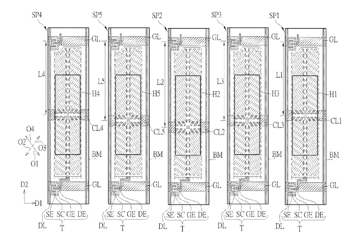
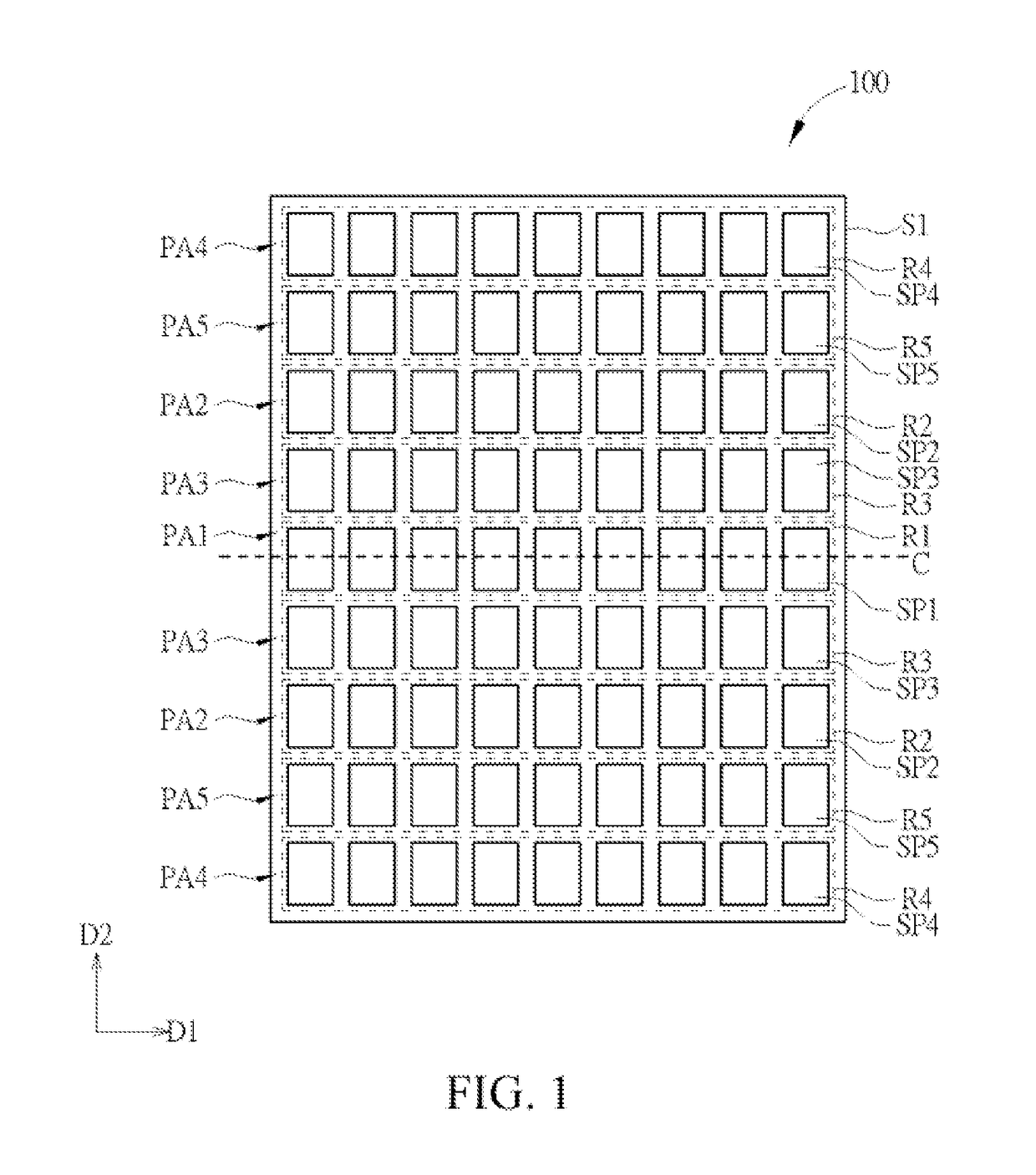
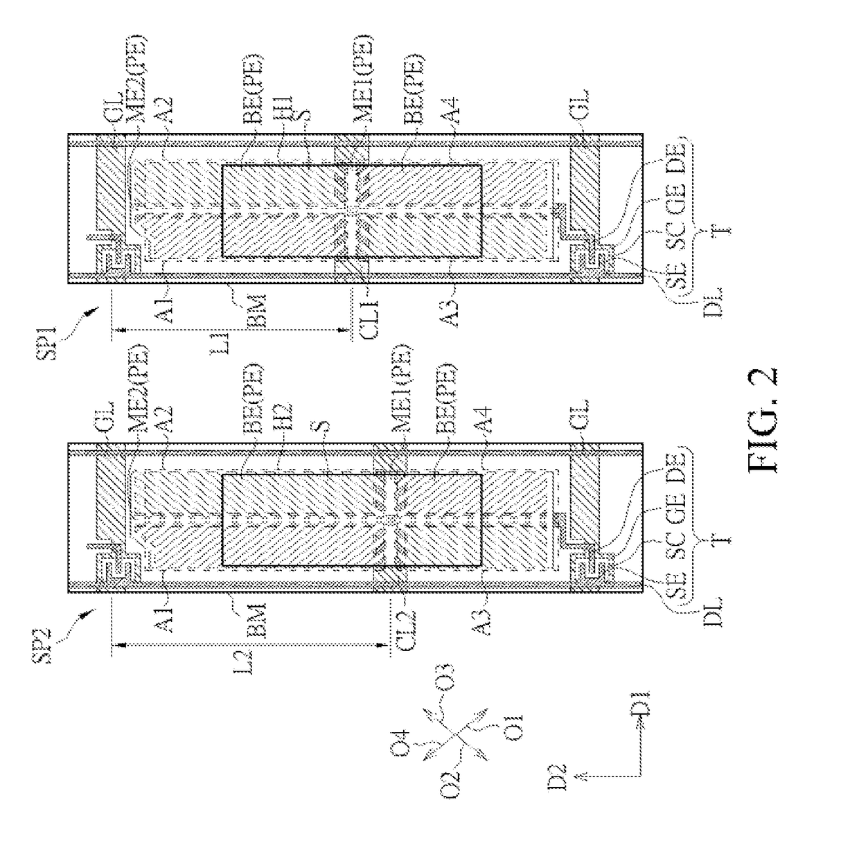
The invention is about a new display panel design that solves issues like light leakage and color differences incurred when bending the panel. The design ensures that the positions of common lines in sub-pixels are not exactly the same, which reduces the impact of bending on the overall display quality.

Problems solved by technology

However, because a relative displacement may occur between the patterned light-shielding layer disposed on the opposing substrate and the shielded region disposed on the array substrate due to the bending of the curved display panel, the patterned light-shielding layer in the curved display panel cannot completely cover the shielded region, and instead light may penetrate a shielded portion, which therefore results in a leakage of light.
In addition, the relative displacement between the patterned light-shielding layer and the array substrate also causes inconsistent alignment configurations of sub-pixels of different regions, resulting in a problem of a color difference in viewing from different view angles, which affects a display effect of the curved display panel.

Method used


Image

  • Display panel
  • Display panel
  • Display panel

Examples


Embodiment Construction

[0020]The present disclosure will now be described more fully hereinafter with reference to the accompanying drawings, in which exemplary embodiments of the invention are shown. This invention may, however, be embodied in many different forms and should not be construed as limited to the embodiments set forth herein. Rather, these embodiments are provided so that this disclosure will be thorough and complete, and will fully convey the scope of the invention to those skilled in the art. Like reference numerals refer to like elements throughout.

[0021]The terms used in this specification generally have their ordinary meanings in the art, within the context of the invention, and in the specific context where each term is used. Certain terms that are used to describe the invention are discussed below, or elsewhere in the specification, to provide additional guidance to the practitioner regarding the description of the invention. For convenience, certain terms may be highlighted, for exam...


PUM

PropertyMeasurementUnit
included angleaaaaaaaaaa
distanceaaaaaaaaaa
distancesaaaaaaaaaa

Abstract

A display panel is divided into a first region and a second region located outside the first region, and includes a first sub-pixel, a second sub-pixel, a plurality of scan lines, a first common line, a second common line, and a black matrix. In the first sub-pixel, a first distance exists between the first common line and a neighboring scan line along a second direction. In the second sub-pixel, a second distance exists between the second common line and a neighboring scan line along the second direction, and the first distance is not equal to the second distance. The black matrix has a plurality of holes, including a first hole and a second hole. The first hole exposes the first sub-pixel and the first common line located in the first region. The second hole exposes the second sub-pixel and the second common line located in the second region.

Description

CROSS-REFERENCE TO RELATED APPLICATIONS[0001]This application claims the priority to and the benefit of, pursuant to 35 U.S.C. §119(a), Taiwanese Patent Application No. 104134285, filed Oct. 20, 2015, the content of which is incorporated herein in its entirety by reference.TECHNICAL FIELD[0002]The present disclosure relates generally to a display panel, and in particular, to a display panel having a balanced alignment mechanism.BACKGROUND[0003]Typically, in a general method for fabricating a curved display panel, a flat display panel (DISPLAY PANEL) may be bent to fabricate a curved display panel. Generally, a patterned light-shielding layer (for example, a black matrix) is configured on an opposing substrate of a display panel to shield a region, where an opaque element (for example, a signal line and a switch element) is configured on an array substrate and a region where a problem of a leakage of light may occur at an edge of the signal line (the regions are generally referred to...

Claims


Application Information

Patent Timeline
Patent Type & Authority Applications(United States)
IPC IPC(8): G02F1/1343G02F1/1333G02F1/1368G02F1/1335H01L27/12G02F1/1362
CPCG02F1/134309H01L27/124G02F1/136286G02F2001/134345G02F1/133512G02F1/133305G02F2201/123G02F1/1368G02F1/1337H01L27/1218G02F1/134345
Inventor CHU, KUNG-CHINGCHEN, JU-CHINSU, SUNG-YU
Owner AU OPTRONICS CORP
Learn More