Eureka AIR delivers breakthrough ideas for toughest innovation challenges, trusted by R&D personnel around the world.

Force-sensing touch screen input device

a touch screen input and force sensor technology, applied in the field of tactile input devices, can solve the problems of increased price and size of the input device, extra reliability, and array of thin film pressure sensors underneath the display, and achieve the effect of low thickness and high reliability

Inactive Publication Date: 2017-04-13
PRESSURE PROFILE SYST +1
View PDF0 Cites 31 Cited by
  • Summary
  • Abstract
  • Description
  • Claims
  • Application Information

AI Technical Summary

Benefits of technology

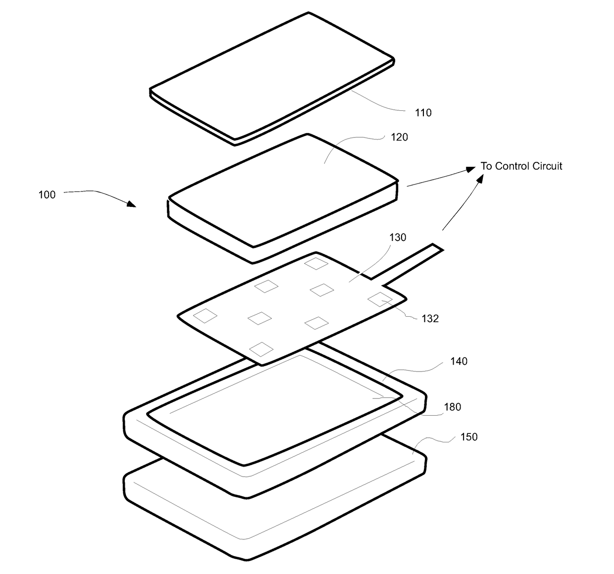
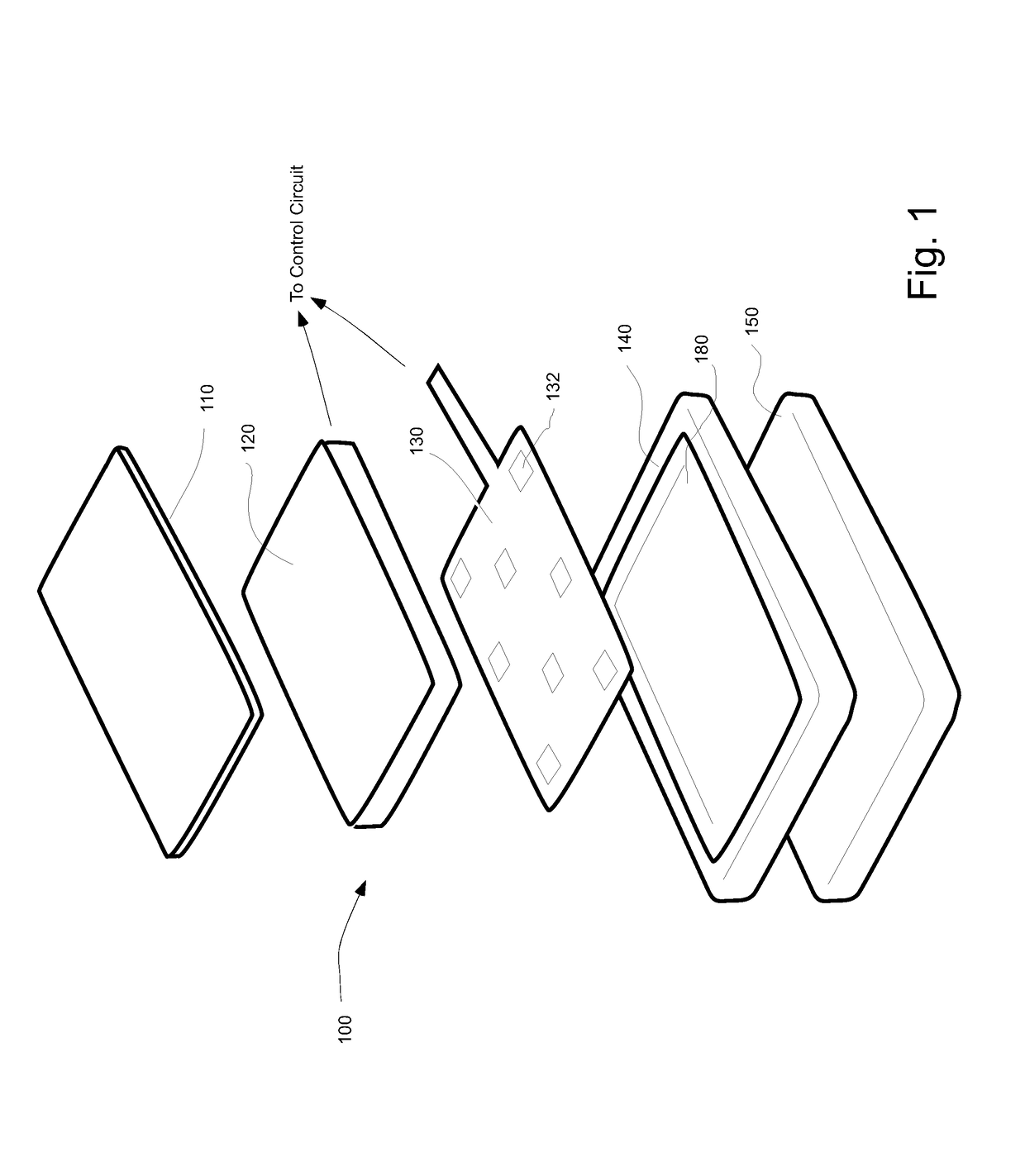
This patent describes a force-sensing touch input device for electronic devices that can detect touch and external force. The device has a thin design and is easy to use, while being cost-effective to manufacture. It includes a touch screen display and a flexible cover glass, and the layers are permanently adhered to each other to ensure high reliability. The device can provide accurate input readings even when used in portable electronic devices that are prone to shock and vibration. Overall, this invention provides a reliable and efficient input mechanism for electronic devices.

Problems solved by technology

This may further increase the price and size of the input device to accommodate the different circuits in the device or require more complex signal transfers to external electronic and processing components.
Straight forward deployment of an array of thin film pressure sensors underneath the display presents a disadvantage of being too expensive because of multiple layers of electrodes needed to fabricate the sensor.
Using such devices in cellular phones, tablets or other electronics dictates a requirement of extra reliability as these devices may be occasionally dropped, mishandled, compressed or subjected to other conditions of shock and vibration.

Method used


Image

  • Force-sensing touch screen input device
  • Force-sensing touch screen input device
  • Force-sensing touch screen input device

Examples


Embodiment Construction

[0038]The following description sets forth various examples along with specific details to provide a thorough understanding of claimed subject matter. It will be understood by those skilled in the art, however, that claimed subject matter may be practiced without one or more of the specific details disclosed herein. Further, in some circumstances, well-known methods, procedures, systems, components and / or circuits have not been described in detail in order to avoid unnecessarily obscuring claimed subject matter. In the following detailed description, reference is made to the accompanying drawings, which form a part hereof. In the drawings, similar symbols typically identify similar components, unless context dictates otherwise. The illustrative embodiments described in the detailed description, drawings, and claims are not meant to be limiting. Other embodiments may be utilized, and other changes may be made, without departing from the spirit or scope of the subject matter presented...


PUM


Abstract

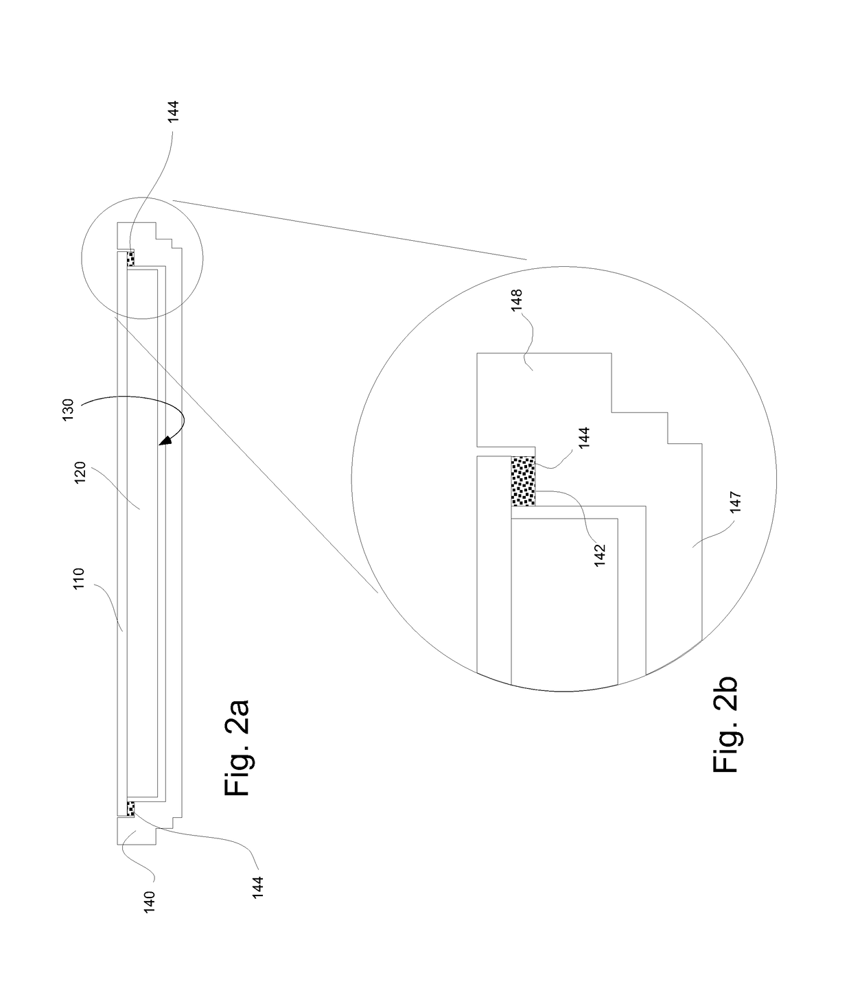
A force sensing touch screen input device is a solid assembly of multiple layers including a display with a touch-sensitive external surface, a first and second electrode layers separated by a compressible dielectric structure—forming a capacitive force-sensing array, and a rigid planar substrate. One or both electrode layers may be formed by metallizing a polymer surface of the rigid substrate or by creating a conductive electrode onto an internal surface of the display. To increase reliability, each layer is permanently adhered to or formed onto an adjacent layer over its entire surface, whereby preventing internal shifts therebetween. To increase response time, the cover glass flexibility, compressible dielectric structure and the gasket structure between the cover glass and the rigid planar substrates are selected to provide elastic compression and recovery during normal operating conditions.

Description

CROSS-REFERENCE DATA[0001]This application claims a priority date benefit from a U.S. Provisional Patent Application No. 62 / 239,919 filed 11 Oct. 2015 with the same title, the content of which is incorporated herein by reference in its entirety.BACKGROUND OF THE INVENTION[0002]This present invention generally relates to tactile input devices and more specifically to tactile input devices with integral touch input surfaces and force-measuring capability.[0003]Tactile input devices, that quantify the level of force being applied to a surface, are becoming more popular in a variety of applications. Cellular telephones, smartphones, tablets, laptops, personal digital assistants (PDAS), “smart” watches and other electronic devices seek to incorporate greater numbers of functions in such devices for a given volume. Tactile input devices can provide this capability. This has led to a number of approaches for providing input devices that utilize capacitive, resistive, strain gauge and other...

Claims


Application Information

Patent Timeline
IPC IPC(8): G06F3/041G06F3/044
CPCG06F3/0414G06F2203/04102G06F3/044G06F3/0412G06F3/0416G06F3/0447
Inventor SON, JAE S.HAN, SANG YOUL
Owner PRESSURE PROFILE SYST
Why Eureka
Eureka Blog
Learn More