
Method and apparatus for wireless charging using variable switching frequency

a variable switching frequency and wireless charging technology, applied in the direction of charging stations, electric vehicle charging technology, transportation and packaging, etc., can solve the problems of hard switching damage, reduced output power and power transfer efficiency, and difficulty in transferring power to an output, so as to prevent hard switching damage to the switch in the dc-to-dc convertor. , the effect of output voltag

Active Publication Date: 2017-04-13
HYUNDAI MOTOR CO LTD
View PDF0 Cites 8 Cited by
  • Summary
  • Abstract
  • Description
  • Claims
  • Application Information

AI Technical Summary

Benefits of technology

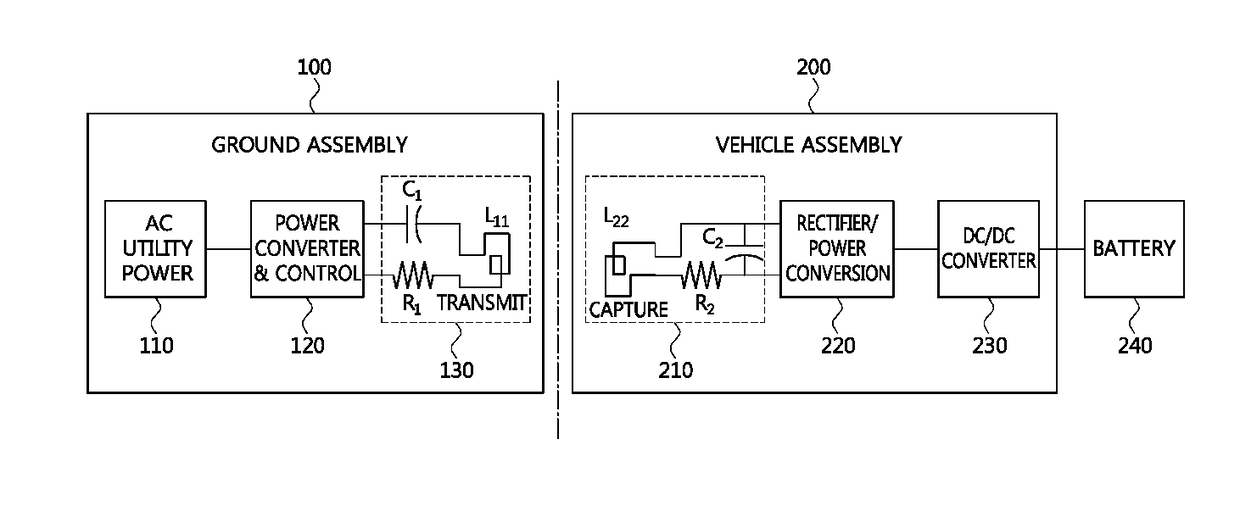
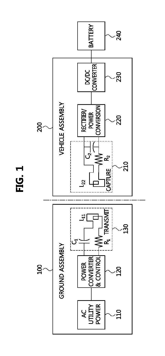
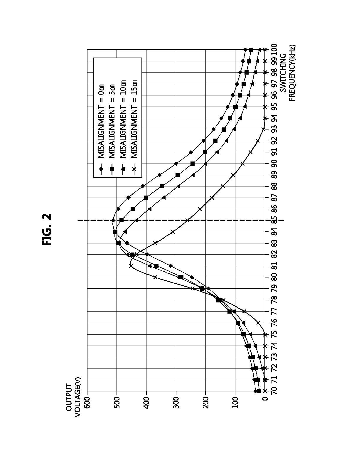
The present patent describes a wireless charging method that uses variable switching frequency to detect wireless power parameters and compensate for misalignment between the primary and secondary pads. This method has advantages of output voltage and efficiency degrading gradually even if there is misalignment. Additionally, the duty of the DC-to-DC convertor is maintained as its maximum value while determining an optimal switching frequency, which prevents damage to the switch and ensures zero voltage switching (ZVS) region broadening.

Problems solved by technology

That is, since magnetizing inductance is much larger than leakage inductance, it may become difficult to transfer power to an output.
However, when a misalignment between the primary pad and the secondary pad exists, the magnetizing inductance and the leakage inductance may vary, and consequently, the resonance between the pads degrades, and the output power and efficiency of the power transfer decrease.
Also, due to manufacturing tolerances of the primary pad, secondary pad, and capacitor, the resonance between the pads may degrade so that the output power and efficiency of the power transfer decrease.

Method used


Image

  • Method and apparatus for wireless charging using variable switching frequency
  • Method and apparatus for wireless charging using variable switching frequency
  • Method and apparatus for wireless charging using variable switching frequency

Examples


Embodiment Construction

[0046]Example embodiments of the present disclosure are disclosed herein. However, specific structural and functional details disclosed herein are merely representative for purposes of describing example embodiments of the present disclosure, however, example embodiments of the present disclosure may be embodied in many alternate forms and should not be construed as limited to example embodiments of the present disclosure set forth herein. While describing the respective drawings, like reference numerals designate like elements.

[0047]The terminology used herein is for the purpose of describing particular embodiments only and is not intended to be limiting of the disclosure. As used herein, the singular forms “a,”“an,” and “the” are intended to include the plural forms as well, unless the context clearly indicates otherwise. It will be further understood that the terms “comprises” and / or “comprising,” when used in this specification, specify the presence of stated features, integers,...


PUM


Abstract

A wireless charging method performed by a wireless power receiving apparatus for a vehicle includes: producing a resonance between a primary pad located outside of the vehicle and a secondary pad installed in the vehicle based on an initial switching frequency; and tuning a switching frequency of a direct current (DC) to DC (DC-to-DC) converter within a range determined based on the initial switching frequency, according to an output voltage outputted based on a resonance of the secondary pad which is caused by the primary pad.

Description

CROSS-REFERENCE TO RELATED APPLICATION[0001]This application claims the benefit of and priority to Korean Patent Application No. 2015-0142182 filed on Oct. 12, 2015 in the Korean Intellectual Property Office (KIPO), the entire contents of which are hereby incorporated by reference as if fully set forth herein.BACKGROUND[0002]1. Technical Field[0003]The present disclosure relates generally to a wireless charging method for a vehicle, and more particularly, to a method and an apparatus using a variable switching frequency in order to obtain a target output voltage.[0004]2. Related Art[0005]Due to environmental pollution and oil energy depletion, world-wide studies on environment-friendly electric vehicles (EV) have been ongoing. As demands and developments relating to EVs and plug-in hybrid vehicles (PHEV) increase, the on-board charger (OBC) for high-voltage battery charging becomes an essential component in the automobile industry.[0006]Meanwhile, instead of conductive charging for ...

Claims


Application Information

Patent Timeline
Patent Type & Authority Applications(United States)
IPC IPC(8): B60L11/18H02J7/02H02J7/00H02J50/12
CPCB60L11/182H02J50/12H02J2007/0059H02J7/0052H02J7/025Y02T10/7072Y02T90/14B60L53/60B60L53/12H02J2207/20H02J2310/48Y02T90/12Y02T10/70H02J7/007H02J7/00Y02T90/16
Inventor SEONG, HYUN WOOKLEE, WOO YOUNGCHOE, GYU YEONG
Owner HYUNDAI MOTOR CO LTD
Learn More