Charging rate leveling device and power supply system

Active Publication Date: 2017-04-06
YAZAKI CORP
View PDF6 Cites 20 Cited by
  • Summary
  • Abstract
  • Description
  • Claims
  • Application Information

AI Technical Summary

Benefits of technology

The charging rate leveling device described in this patent text is designed to quickly level the charging rates of multiple battery cells in a battery pack. It includes an auxiliary battery and a discharging connection selector that can connect each battery cell to the auxiliary battery for charging. By selectively connecting the highest or lowest voltage battery cell to the auxiliary battery, the device can transfer large amounts of electric charge to reduce the difference in charging rates between cells. This allows for faster leveling of the battery cells and reduces the need for frequent charging. The device also includes a battery cell detector and a charging rate detector to help select the best battery cell for charging. Overall, this device helps to prolong the life of battery cells and improve the overall performance of battery packs.

Problems solved by technology

Because charge or discharge of the battery module is made in conformity with degraded battery cells, the other battery cells not degraded cannot be fully consumed, resulting in actual decrease of whole capacity of battery module in conformity with the battery cell degraded.

Method used


Image

  • Charging rate leveling device and power supply system
  • Charging rate leveling device and power supply system
  • Charging rate leveling device and power supply system

Examples


first embodiment

[0028]Hereinafter, regarding a charging rate leveling device of the first embodiment of the present invention and a power supply system including the same will be explained with reference to FIGS. 1 to 5.

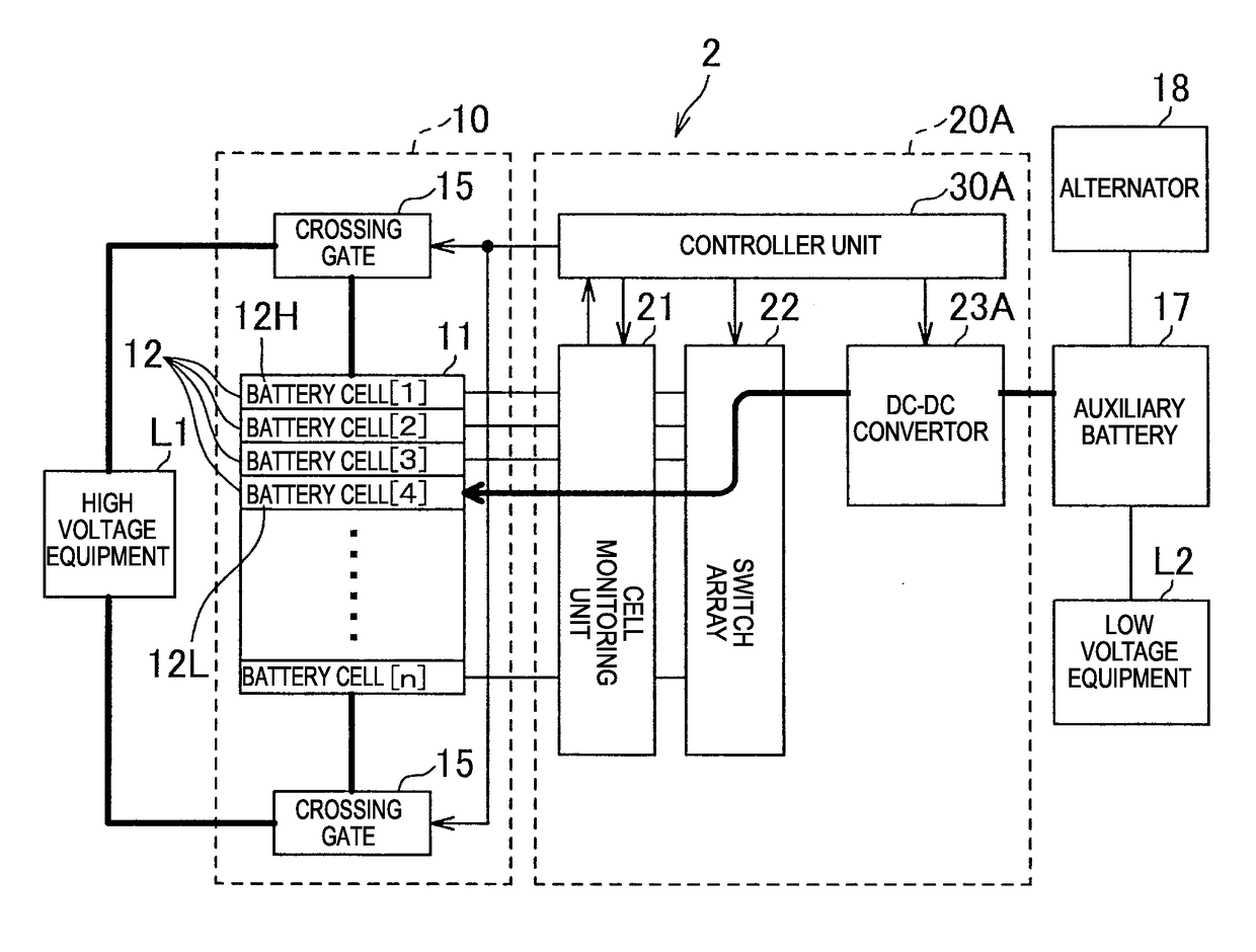
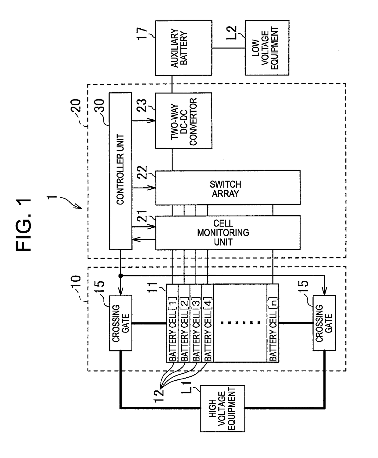
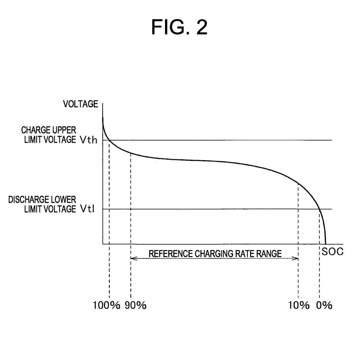
[0029]FIG. 1 is a view illustrating a schematic configuration of a power supply system of the first embodiment of the present invention. FIG. 2 is a view schematically illustrating relationship between a voltage between both electrodes of a battery cell a battery pack of the power supply system in FIG. 1 includes and a charging rate. FIG. 3 is a flowchart illustrating one example of charging rate leveling process 1 a controller of control device of the power supply system in FIG. 1 performs. FIG. 4 is a view schematically illustrating transferring electric charge from the battery cell to the auxiliary battery in the power supply system in FIG. 1. FIG. 4 is a view schematically illustrating transferring of electric charge from a battery cell to the auxiliary battery in the power supp...

second embodiment

[0071]Hereinafter with reference to FIGS. 6 to 8, a charging rate leveling device of the second embodiment and a power supply system including the same will be described.

[0072]FIG. 6 schematically illustrates a configuration of the power supply system of the second embodiment of the present invention. FIG. 7 is the flowchart illustrating one example of a charging rate leveling process 2 the controller of the control device of the power supply system in FIG. 6 executes. FIG. 8 is a view schematically illustrating transferring charge from the auxiliary battery to battery cell in the power supply system in FIG. 6.

[0073]The power supply system of the present embodiment, as similar to the power supply system of the abovementioned first embodiment, for example, is mounted in a vehicle such as electric vehicle, supplies electric power to a high voltage equipment such as electric motor of the vehicle, levels charging rate of the plurality of battery cells the battery pack of the power suppl...


PUM


Abstract

Provided are a charging rate leveling device and a power supply system including the charging rate leveling device capable of leveling more quickly a charging rate of a plurality of battery cells a battery pack includes. In the power supply system a controlling device includes a two-way DC / DC convertor connected to an auxiliary battery separated from the battery pack, a switch array capable of selectively connecting each of the plurality of auxiliary battery cells the battery pack includes to the two-way DC / DC convertor, so as to charge the battery cell with electric power of the auxiliary battery, and a controller controlling the switch array to connect the lowest voltage battery cell selected among the plurality of battery cells, so as to reduce a difference between charging rates SOC of each of the plurality of battery cells.

Description

FIELD OF THE INVENTION[0001]The present invention is related to a charging rate leveling device leveling a charging rate of a plurality of cells a battery pack includes and a power supply system having the same.DESCRIPTION OF THE RELATED ART[0002]In various vehicles such as an electric vehicle (EV) running with an electric motor, or a hybrid electric vehicle (HEV) running together with an engine and an electric motor, mounted as a power source for electric motor is a battery module including a battery pack having a plurality of battery cells (unit cell) composed of a secondary battery such as lithium ion battery or nickel hydride battery.[0003]Since a large electric power is required for operating such electric motor, a plurality of battery cells is connected in series in order to output high voltage in the battery module. For the plurality of such battery cells of the battery module, resulting from individual difference or deviation of circumferential temperature, a part battery ce...

Claims


Application Information

Patent Timeline
IPC IPC(8): H02J7/00H01M10/48G01R31/36
CPCH02J7/0016H01M10/48G01R31/362H02J7/0021H01M10/441H01M10/482H02J7/0019H02J7/342Y02T10/70Y02E60/10H02J7/0048H02J7/005G01R31/3835
Inventor SYOUDA, TAKAHIRO
Owner YAZAKI CORP
Why Eureka
Try Eureka