
Antenna communication system and antenna integrated smart device thereof

a communication system and smart device technology, applied in the field of antennas, can solve the problems of reducing the operation efficiency of the cellular communication network, tedious and time-consuming, and reducing profits

Inactive Publication Date: 2017-03-30
SKY ALIGN SOLUTIONS PTE LTD
View PDF5 Cites 10 Cited by
  • Summary
  • Abstract
  • Description
  • Claims
  • Application Information

AI Technical Summary

Benefits of technology

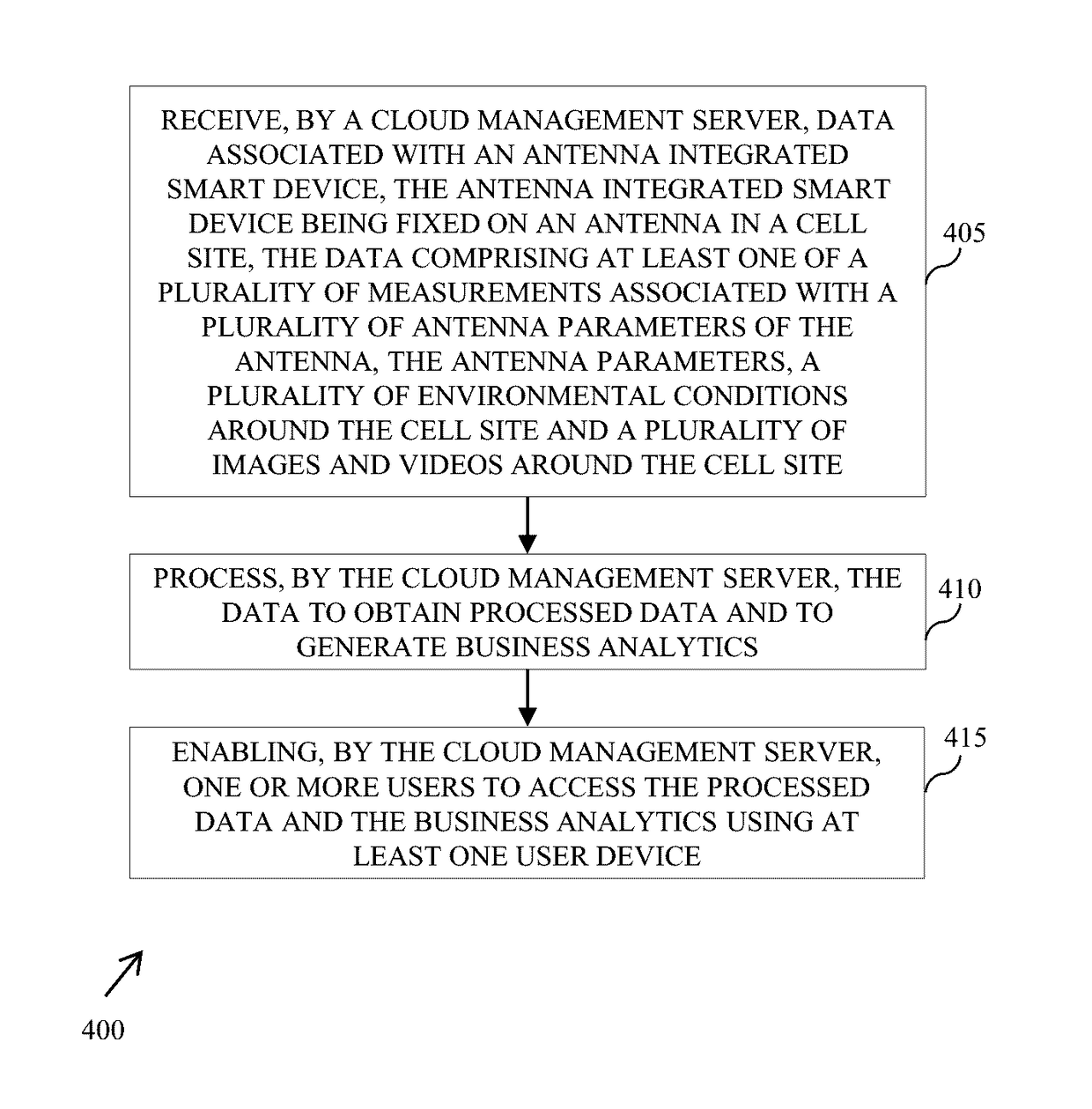
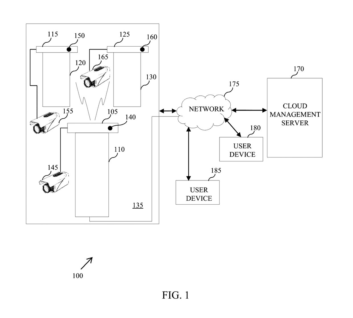
This patent describes an antenna integrated smart device that can collect data associated with an antenna in a cell site and send it to a cloud management server. The server processes the data to create business analytics and makes the data available to users through a user device. The technical effect of this invention is improved efficiency and accuracy in collecting and analyzing data from antennas in cell sites, which can aid in optimizing network performance and improve user experience.

Problems solved by technology

The technician, typically, mounts a pole of the antenna, measures antenna orientation parameters (the azimuth and tilt values) and logs corresponding values, which is both tedious and time consuming.
Moreover, there is a delay in such values reaching cellular operators, thereby causing a decrease in operation efficiency of the cellular communication network as well as a reduction of profits.
However, the antenna alignment device is big in size and heavy in weight.
Such devices usually do not provide accurate measurements and cannot be used to perform any extended functions.

Method used


Image

  • Antenna communication system and antenna integrated smart device thereof
  • Antenna communication system and antenna integrated smart device thereof
  • Antenna communication system and antenna integrated smart device thereof

Examples


Embodiment Construction

[0018]For the purpose of promoting an understanding of the principles of the invention, reference will now be made to the embodiment illustrated in the figures and specific language will be used to describe the same. It will nevertheless be understood that no limitation of the scope of the invention is thereby intended, such alterations and further modifications in the illustrated system, and such further applications of the principles of the invention as illustrated therein being contemplated as would normally occur to one skilled in the art to which the invention relates.

[0019]It will be understood by those skilled in the art that the foregoing general description and the following detailed description are exemplary and explanatory of the invention and are not intended to be restrictive thereof.

[0020]The terms “comprises”, “comprising”, or any other variations thereof, are intended to cover a non-exclusive inclusion, such that a process or method that comprises a list of steps doe...


PUM


Abstract

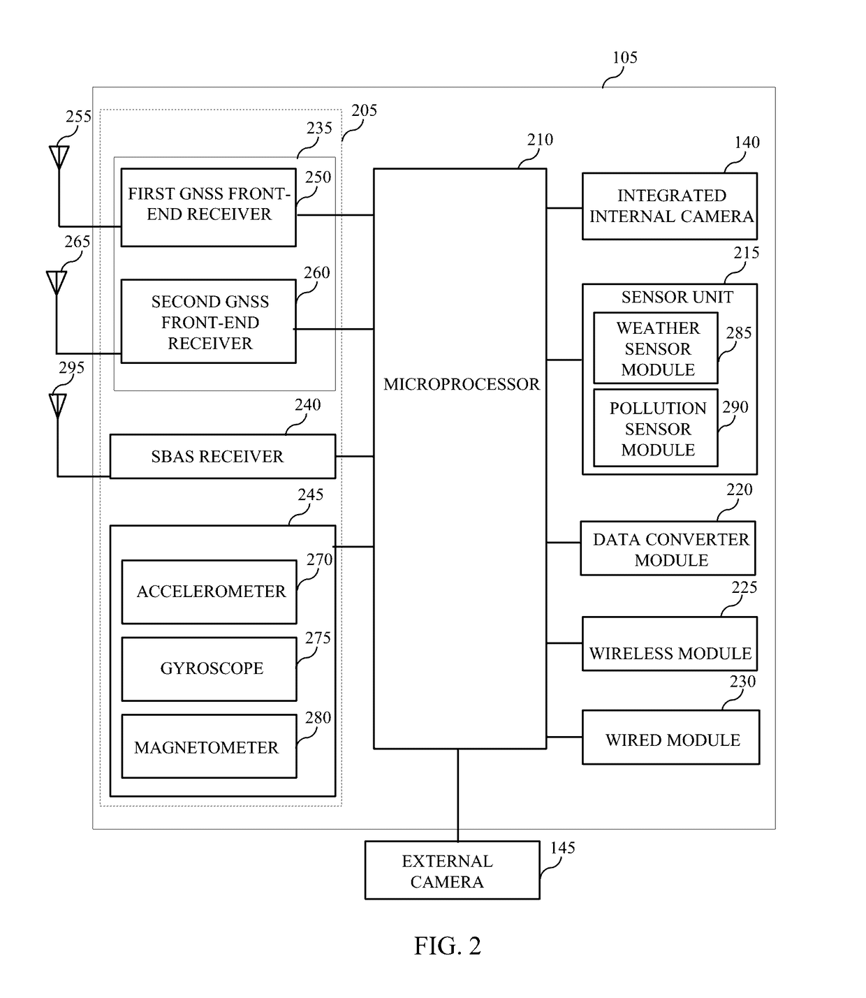
The present invention relates to an antenna communication system and antenna integrated smart device thereof. The device includes an antenna measurement unit, a microprocessor, a sensor unit, and an integrated internal camera. The antenna measurement unit is configured to determine a plurality of measurements associated with a plurality of antenna parameters of an antenna in a cell site. The antenna parameters include antenna azimuth, antenna tilt, antenna roll, antenna height and antenna geographical coordinates. The microprocessor is coupled to the antenna measurement unit and is configured to process the plurality of measurements to determine the plurality of antenna parameters. The sensor unit is coupled to the microprocessor and is configured to sense a plurality of environmental conditions around the cell site. The integrated internal camera is coupled to the microprocessor and is configured to capture a first set of images and a first set of videos around the cell site.

Description

CROSS REFERENCE TO RELATED APPLICATIONS[0001]The present application claims priority to Indian patent application number 3711 / MUM / 2015 filed on 30 Sep. 2015, which is incorporated herein by reference.FIELD OF THE INVENTION[0002]The present invention generally relates to antennas and more particularly to an antenna communication device and an antenna integrated smart device thereof.[0003]BACKGROUND TO THE INVENTION[0004]In a cellular telecommunication network, azimuth (or direction) and tilt values of an antenna determines a coverage area of a cell site (also referred to as a base station or cell tower). The azimuth and tilt values are typically derived from exhaustive computations. The antenna must then be installed precisely in a particular direction and be given a tilt according to the azimuth and tilt values, respectively, based on the computations. Orientation of the antenna changes over a period of time due to a continuous radio frequency (RF) optimization process. Further, cha...

Claims


Application Information

Patent Timeline
IPC IPC(8): G01R29/10H04W72/04H04M15/00H04W24/02
CPCG01R29/10H04M15/58H04W72/046H04W24/02
Inventor BAGUL, RAJESH SHANTARAMSRIWASTAVA, SHARAD
Owner SKY ALIGN SOLUTIONS PTE LTD
Learn More