
Column settler for high performance liquid/liquid phase separations in hydromellurcial processes and methods thereof

a technology of liquid/liquid phase separation and column settler, which is applied in the direction of solvent extraction, separation process, liquid solution solvent extraction, etc., can solve the problems of increasing manufacturing costs and achieve the effect of reducing the necessary footprint area

Inactive Publication Date: 2017-03-23
BACZEK FR +1
View PDF8 Cites 1 Cited by
  • Summary
  • Abstract
  • Description
  • Claims
  • Application Information

AI Technical Summary

Benefits of technology

The patent is about an improved settler for solvent extraction that reduces the size of the equipment needed and speeds up the process. It also reduces the formation of crud and improves the separation of different liquids. The settler can be equipped with gentle agitation means, such as baffles or slow rotation means, to promote the coalescence of different liquids.

Problems solved by technology

The settling stage is massive, requires very large footprints, and requires long distances of piping and tubing, therefore increasing manufacturing costs.

Method used


Image

  • Column settler for high performance liquid/liquid phase separations in hydromellurcial processes and methods thereof
  • Column settler for high performance liquid/liquid phase separations in hydromellurcial processes and methods thereof
  • Column settler for high performance liquid/liquid phase separations in hydromellurcial processes and methods thereof

Examples


Embodiment Construction

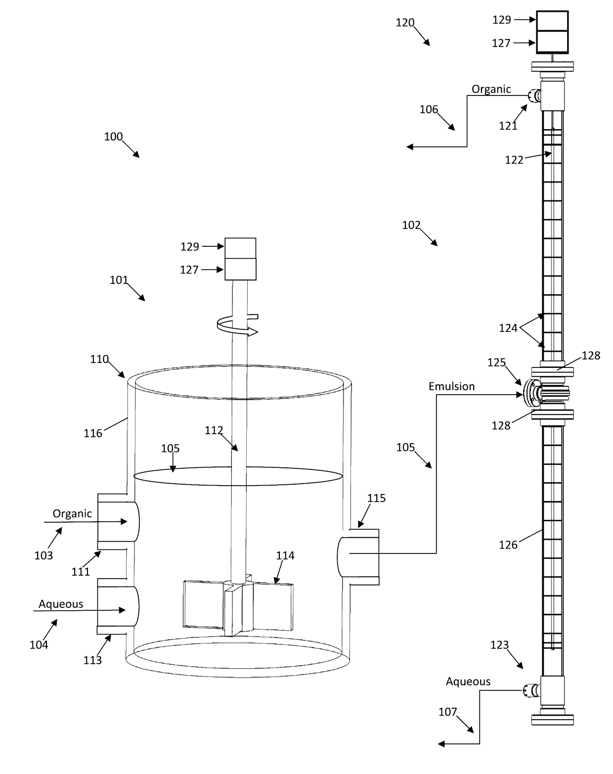
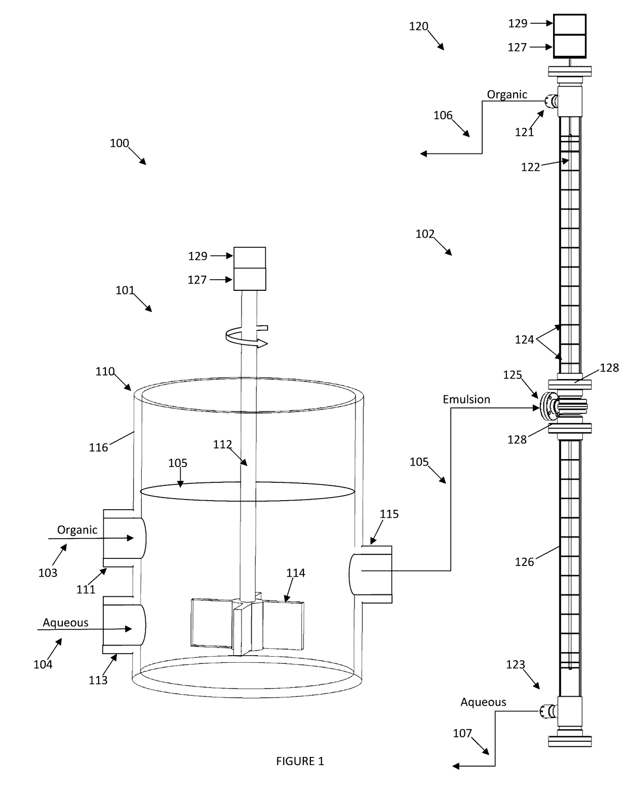
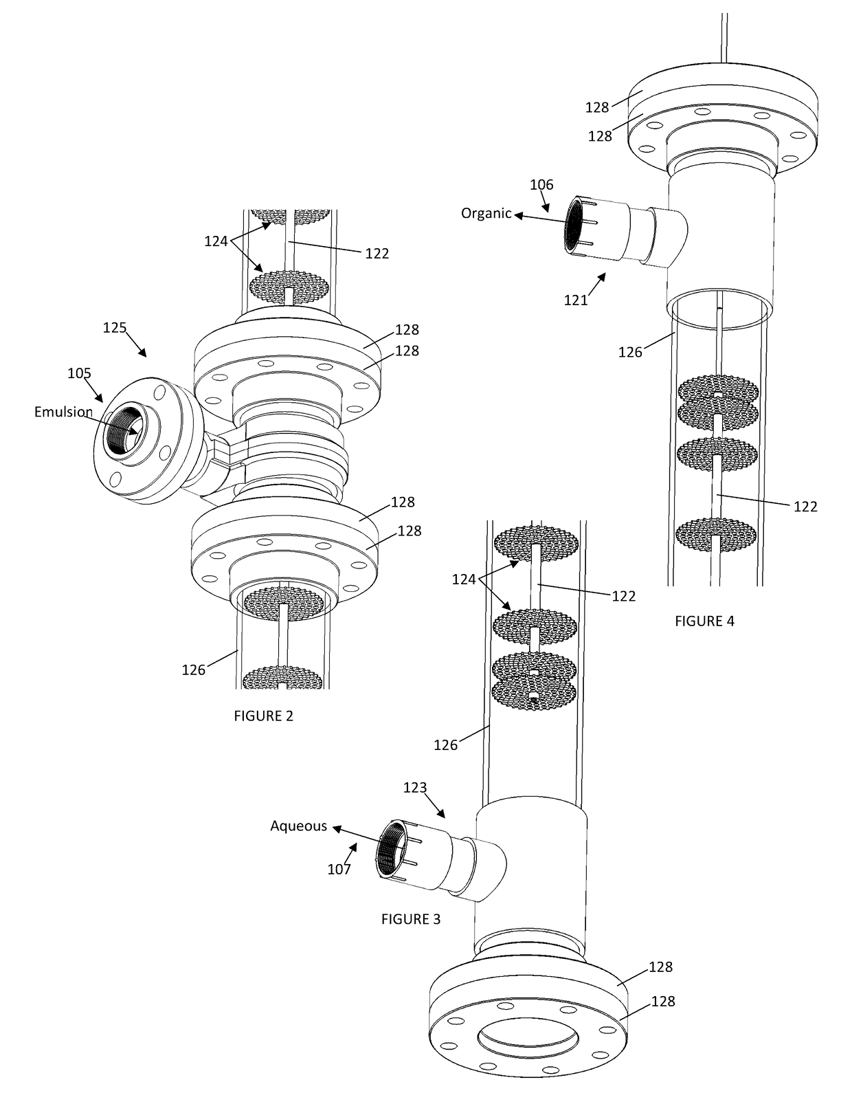
[0035]Turning now to FIGS. 1-5, a mixer-settler system 100 is provided, the system having a mass transfer step 101 and a gravity settling step 102. The mass transfer step 101 comprises receiving a first organic phase 103 and receiving a first aqueous phase 104 into a mixer 110. The mixer 110 has an organic inlet 111 and an aqueous inlet 113 for receiving the respective first organic phase 103 and first aqueous phase 104 into the mixer 110. The first organic phase 103 and first aqueous phase 104 may, via high energy inputs, be mixed into a mixed unstable emulsion phase 105 via a rotating mixing shaft 112 and impeller 114 provided to the mixer 110. The mixing shaft 112 is rotated via a motor 129 and an optional transmission, gearbox, or variable frequency drive (VFD) 127. Preferably, the RPM of the mixing shaft 112 and the impeller 114 design is configured for mixing the first organic phase 103 with the first aqueous phase 104, and / or maintaining a mixed unstable emulsion phase 105. T...


PUM

PropertyMeasurementUnit
mass transferaaaaaaaaaa
mass transfersaaaaaaaaaa
angleaaaaaaaaaa

Abstract

A mixer settler system is disclosed. The system comprises a mixer [110] configured for receiving an organic phase and an aqueous phase, the mixer [110] being further configured to maintain the organic phase and the aqueous phase in a single unstable emulsion phase, wherein mass transfer occurs between said organic phase and said aqueous phase; and, a column settler [120] which is configured to receive a single unstable emulsion phase from the mixer [110] via an emulsion inlet [125] and is also configured to separate the single unstable emulsion phase into a stable organic phase and a stable aqueous phase by virtue of coalescence; the column settler further comprising an organic outlet [121] above the emulsion inlet [125] and an aqueous outlet [123] below the emulsion inlet [125]; the column settler [120] further discouraging mass transfers within the unstable emulsion phase and further promoting coalescence of each of said stable organic phase and stable aqueous phase. A method of settling two immiscible liquids is further disclosed. The method comprises providing a mixer [110] configured for receiving an organic phase and an aqueous phase; maintaining the organic phase and the aqueous phase in a single unstable emulsion phase using the mixer [110], wherein mass transfer occurs between said organic phase and said aqueous phase; providing a column settler [120] which is configured to receive a single unstable emulsion phase from the mixer [110]; sending the single unstable emulsion phase to the column settler [120]; and separating the single unstable emulsion phase into a stable organic phase and a stable aqueous phase within the column settler [120] by virtue of coalescence.

Description

FIELD OF THE INVENTION[0001]This invention relates to settling devices such as mixer settlers commonly used in solvent extraction processes, and more particularly to systems for and methods of quickly settling an organic phase from an aqueous phase, and vice-versa with minimal footprint and high throughput.BACKGROUND OF THE INVENTION[0002]Mixer settlers are a class of mineral process equipment used in solvent extraction processes. Mixer settlers generally consist of a first stage that mixes two immiscible phases together, followed by a quiescent settling stage that allows the phases to separate by gravity.[0003]To this end, bulky mixer settlers require, on average, larger than 15×30×1 meter settling stage equipment, and up to three pieces of mixer stage equipment (e.g., primary and auxiliary mixers). Each stage of the mixer stage performs a combined pumping and mixing action. Use of multiple stages allows a longer reaction time and also minimizes the short circuiting of unreacted ma...

Claims


Application Information

Patent Timeline
Patent Type & Authority Applications(United States)
IPC IPC(8): B01D11/04B01D17/02B01D17/04
CPCB01D11/0457B01D17/0211B01D11/048B01D17/041B01D11/0446B01D17/02C22B3/00
Inventor BACZEK, FRANKCHAIKO, DAVID J.GUPTA, VISHALKANDAGATLA, SUMAPOTRATZ, BRYANROY, GARY
Owner BACZEK FR
Learn More