
Water minimizing method and apparatus for use with evaporative cooling devices

a technology of evaporative cooling and water minimizing, which is applied in the direction of indirect heat exchangers, lighting and heating apparatus, heating types, etc., can solve the problems of increasing the cost of operating the system, affecting and wasting cooling water. , to achieve the effect of improving the efficiency and effectiveness of evaporative cooling systems

Inactive Publication Date: 2017-03-16
MANTERS CORP
View PDF2 Cites 12 Cited by
  • Summary
  • Abstract
  • Description
  • Claims
  • Application Information

AI Technical Summary

Benefits of technology

The present invention improves the cooling efficiency of evaporative cooling systems by using bleed off cooling water in a supplemental cooling process. This reduces the amount of water wasted and increases the amount of work done by the system. It also offers an alternative to water pre-treatment or chemical treatment to reduce bleed water requirements and total water usage. This invention can be used alone or in conjunction with other techniques.

Problems solved by technology

Such can result in substantial waste of cooling water.
This waste can significantly increase the cost of operating the system, present a negative public image of the operator, and also place a significant burden on water supplies, particularly in areas where fresh water is scarce.

Method used


Image

  • Water minimizing method and apparatus for use with evaporative cooling devices
  • Water minimizing method and apparatus for use with evaporative cooling devices
  • Water minimizing method and apparatus for use with evaporative cooling devices

Examples


Embodiment Construction

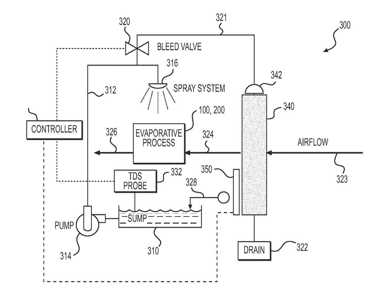
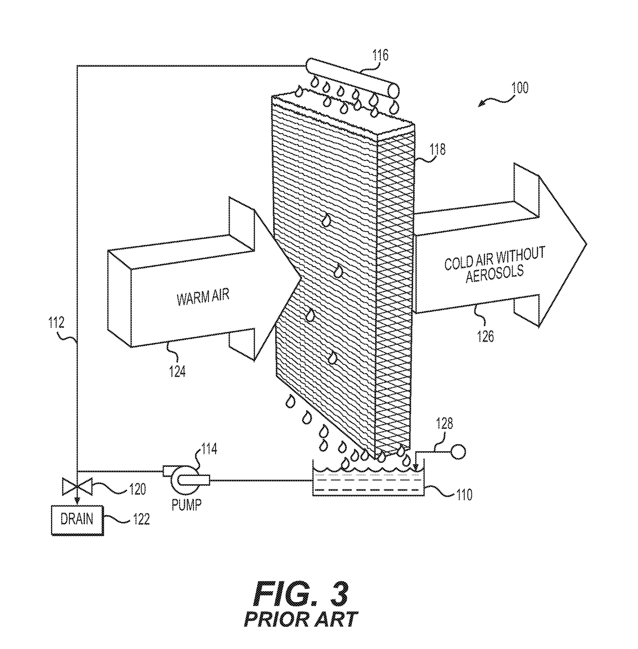
[0024]In a system of the present invention, the bleed water from an evaporative cooler is utilized to cool the air entering an evaporative section of a typical evaporative cooling system, such as a system described above with respect to FIGS. 3 and 4. This is accomplished by passing the bled water over dewatering media, or mineral removal media (MRM), which is itself a direct evaporative cooling section. The mineral removal media cools and humidifies the air before entering a principal evaporative cooling process described above.

[0025]The evaporative cooling device following the MRM media can be of any type, including, as discussed above, the direct evaporative type where water is evaporated into the air as a means to cool the air and the indirect evaporative type where water is evaporated into an air stream as a means to cool a third fluid contained in a heat exchanger that is wetted in the evaporative cooling zone, and even a cooling tower, where water is evaporated to an air stre...


PUM


Abstract

An evaporative cooling system includes a primary cooling unit that utilizes a cooling fluid flowing through a primary heat exchange medium to cool supply air flowing past the primary heat exchange medium, a bleed line and a secondary cooling unit disposed upstream of the primary cooling unit with respect to a flow direction of the supply air. The primary cooling unit includes a supply line for supplying the cooling fluid to the primary heat exchange medium, a reservoir for collecting the cooling fluid supplied to the primary heat exchange medium, and a pump for recirculating the cooling fluid collected in the reservoir back to the supply line. The bleed line bleeds a portion of the recirculating cooling fluid from the primary cooling unit. The secondary cooling unit includes a secondary heat exchange medium that receives the cooling fluid bled from the primary cooling unit through the bleed line. By either pumping or wicking, any excess bleed fluid is refed to the secondary heat exchange medium, or directed to a tertiary heat exchange medium, to enable complete evaporation of the bled fluid.

Description

REFERENCE TO RELATED APPLICATION[0001]This application claims the benefit of U.S. Provisional Patent Application No. 62 / 216,883, filed Sep. 10, 2015.BACKGROUND OF THE INVENTION[0002]1. Field of the Invention[0003]The present invention is directed to improvements in evaporative cooling systems, conditioning systems that utilize thermodynamic laws to cool a fluid. Namely, a change of a fluid from a liquid phase to a vapor phase can result in a reduction in temperature due to the heat of vaporization involved in the phase change.[0004]2. Related Background Art[0005]In a typical evaporative cooler, raw water is supplied to or recirculated through a heat exchanger and is vaporized by extracting heat from supply air flowing through the heat exchanger. Most readily available forms of raw water include various contaminants, most notably dissolved salts and minerals. In a recirculating evaporative cooling system, excess water supplied to the heat exchanger that has not evaporated is collecte...

Claims


Application Information

Patent Timeline
IPC IPC(8): F25B19/00F25B41/04F25B49/00F25B19/02
CPCF25B19/00F25B19/02F25B2500/23F25B49/00F25B2600/2507F25B41/04F24F5/0035F28C1/14F28D5/00F28D5/02F28F25/02Y02B30/54Y02B30/70
Inventor DINNAGE, PAUL A.
Owner MANTERS CORP
Learn More