Cleaning System and Method for Controlling Indoor Hazardous Substances

a technology for cleaning systems and hazardous substances, applied in ventilation systems, lighting and heating apparatuses, heating types, etc., can solve the problems of inability to apply methods to infected sites, extra operations are needed, etc., to reduce the risk of users being exposed, achieve effective large-area disinfection, and improve cleaning effectiveness

Inactive Publication Date: 2017-03-16
TAI CHI PANG
View PDF4 Cites 4 Cited by
  • Summary
  • Abstract
  • Description
  • Claims
  • Application Information

AI Technical Summary

Benefits of technology

The cleaning system described in this patent allows for large-area disinfection and sterilization using an air circulation device with an air exhaust accelerator and a flabellum. The system can also be controlled remotely and can include a daily timing and positioning cleaning procedure. This system is useful for process infected indoor spaces and can help decrease the level of harmful substances to a low level of risk or even harmlusness in a large area. Users can also arrange different kinds of cleaning liquid for the system to conduct more well-directed cleaning works. Overall, the cleaning system improves cleaning effectiveness and reduces risks of exposing users to infected spaces.

Problems solved by technology

However, as the ultraviolet ray could not cover hidden areas completely, extra operations are needed to clear up the site first in order to sufficiently expose the surface to be disposed under the ultraviolet ray during the disinfection.
Furthermore, this method cannot be applied to infected sites where no ultraviolet lights are installed.

Method used


Image

  • Cleaning System and Method for Controlling Indoor Hazardous Substances
  • Cleaning System and Method for Controlling Indoor Hazardous Substances
  • Cleaning System and Method for Controlling Indoor Hazardous Substances

Examples


Embodiment Construction

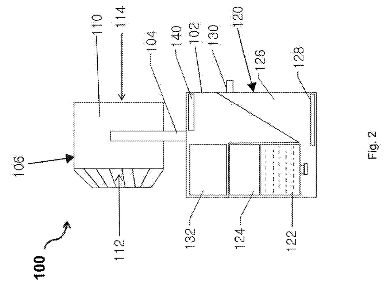
[0031]Embodiments in the present invention adopt the combination of an atomization device and an air circulation device to comprehensively transport the atomized cleaning liquid to every corner of the space. The distinguishing advantages and merits provided by each embodiment can be easily known from the descriptions below.

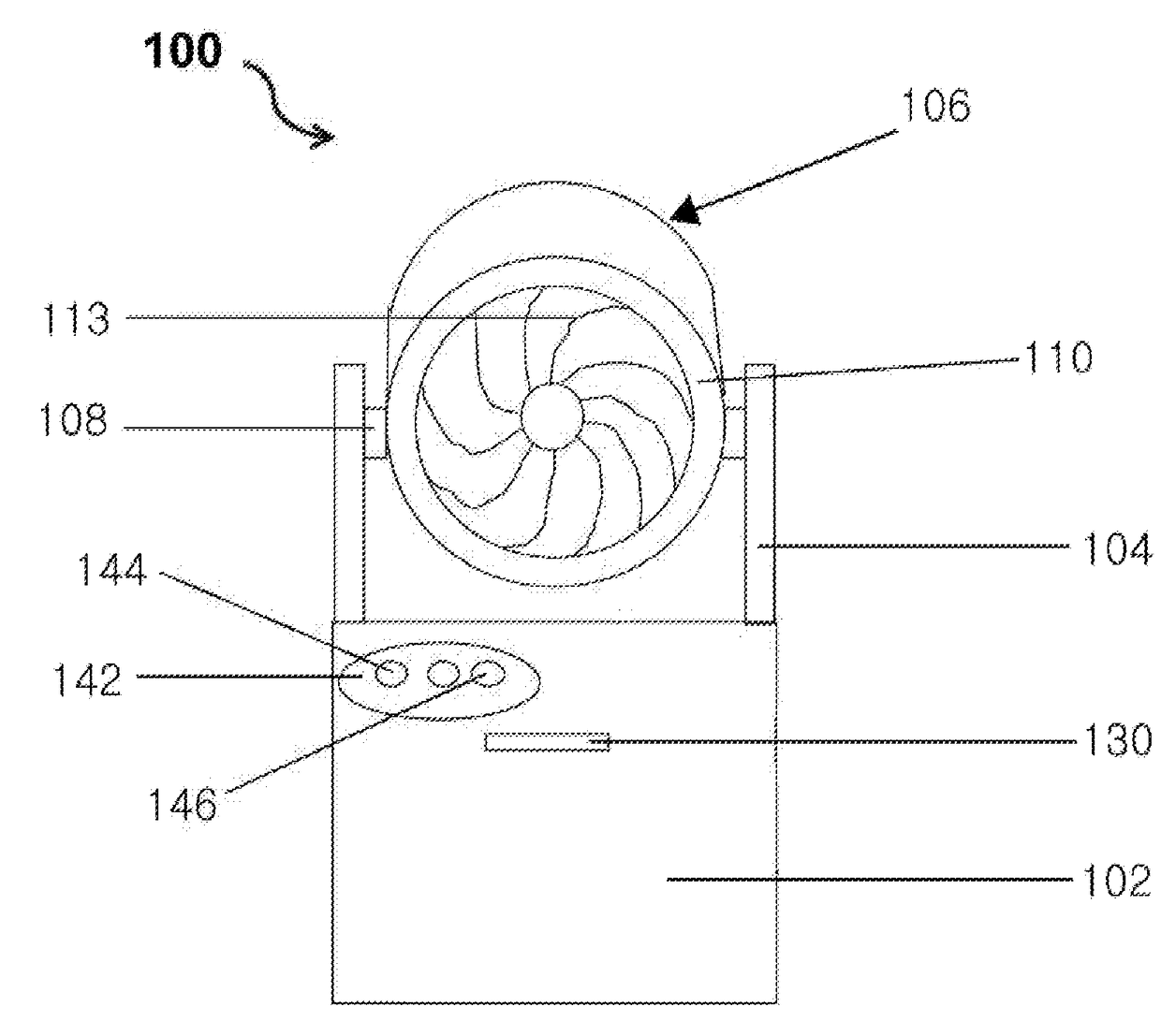
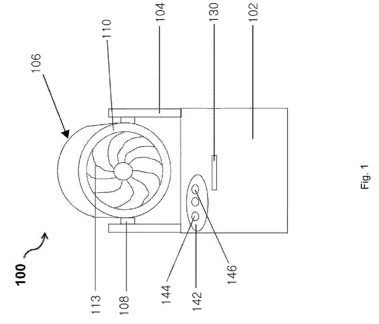
[0032]By referring to FIGS. 1 and 2, the first embodiment of the present invention provides a cleaning system 100 for controlling indoor harmful substances. The cleaning system 100 contains a housing 102 which is arranged with a support 104 to support the air circulation device 106. In the present embodiment, the air circulation device 106 is an air circulation fan 110 which can be pivotally connected to the pivot 108 on the support 104 to facilitate angle adjustment of the air circulation fan 110. The air circulation fan 110 contains a flabellum 113 and a fan cover 112 to generate the vortex flow, and is arranged with an air suction accelerator (not shown) in the...


PUM


Abstract

A cleaning system for controlling indoor harmful substances comprising a housing containing a controlling device to operate the cleaning system; an atomization device atomizing the cleaning liquid; and an air circulation device generating vortex flow to carry the atomized cleaning liquid for indoor circulation, wherein the counterforce of the vortex flow is sent to the inlet of the air circulation device. The cleaning system for controlling harmful substance in the present invention provides multiple advantages which can effectively incorporate large-areal disinfection, sterilization and sterilization by comprehensively transferring the atomized leaning liquid to every corner of the space through the air circulation device and improve the cleaning effectiveness. Meanwhile, the cleaning system in the present invention can be arranged with a remote controlling device so that users can focus on cleaning the local infected area without directly contacting the infected areas so as to reduce the risk of exposing users to the infected space.

Description

FIELD OF INVENTION[0001]The present invention relates to a cleaning system and method for controlling indoor harmful substances. More specifically, it relates to a cleaning system and method for dispersing atomized cleaning liquid in indoor environments.BACKGROUND OF INVENTION[0002]In order to remove indoor pathogenicity substances such as bacterial, virus and fungus, people commonly use ultraviolet ray for indoor space disinfection and sterilization. The ultraviolet ray is commonly used in operating room, dispensary room and the likes in hospitals. However, as the ultraviolet ray could not cover hidden areas completely, extra operations are needed to clear up the site first in order to sufficiently expose the surface to be disposed under the ultraviolet ray during the disinfection. Furthermore, this method cannot be applied to infected sites where no ultraviolet lights are installed. For highly dangerous sites which are suspected to be infected, workers are usually deployed who wea...

Claims


Application Information

Patent Timeline
IPC IPC(8): A61L9/14F24F8/24
CPCA61L2209/13A61L9/145F24F8/117F24F8/10F24F8/24F24F7/007A61L9/14B05B7/0012B05B17/0607A61L2209/11A61L2209/132B05B15/652F24F8/20
Inventor TAI, CHI PANGKWONG, KAM YU
Owner TAI CHI PANG
Why Eureka
Try Eureka