
Producing method of sealed battery

a production method and battery technology, applied in the direction of cell components, final product manufacturing, sustainable manufacturing/processing, etc., can solve the problem that sealed secondary batteries might experience abnormal increase in internal pressure over their normal range, and achieve the effect of suppressing the space present, suppressing the splash, and suppressing the formation of gaps

Active Publication Date: 2017-03-02
TOYOTA JIDOSHA KK
View PDF0 Cites 5 Cited by
  • Summary
  • Abstract
  • Description
  • Claims
  • Application Information

AI Technical Summary

Benefits of technology

The present invention provides a method for joining two parts (a connecting member and an inversion plate) of a sealed battery without causing splash. To achieve this, an inclined surface is formed on at least one of the two parts, allowing for a gradual opening of the space between the two parts during the joining process. The inclined surface is positioned in a way that it comes into contact with the molten portion of the joining process, effectively preventing any space from being partitioned and resulting in a better joint. The method also involves the use of a laser beam to form fixed portions along the boundary of the parts, which helps in preventing deformation and leakage. The width of the joined portion is important for ensuring sufficient joint strength and preventing gaps. Overall, this method creates a more reliable and efficient sealed battery.

Problems solved by technology

Sealed secondary batteries might experience abnormal increase in internal pressure over their normal ranges due to some abnormalities.

Method used


Image

  • Producing method of sealed battery
  • Producing method of sealed battery
  • Producing method of sealed battery

Examples


Embodiment Construction

;

[0036]FIG. 14 is a sectional view in a radial direction of a rivet and an inversion plate of related art; and

[0037]FIG. 15 is a drawing explaining laser beam welding of the related art.

DETAILED DESCRIPTION OF EMBODIMENTS

[0038]A preferable embodiment embodying the present invention will be described in details with reference to drawings, hereinafter.

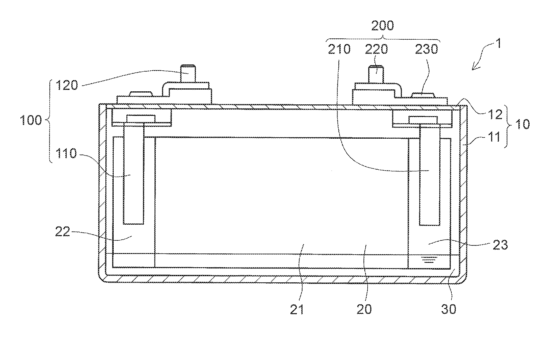
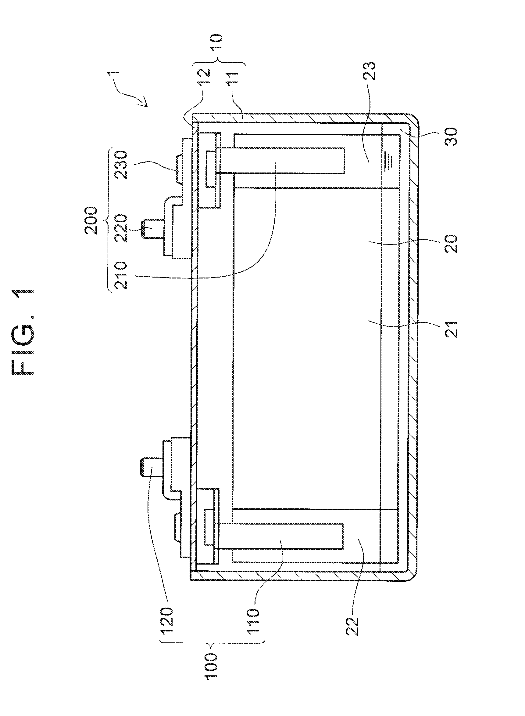
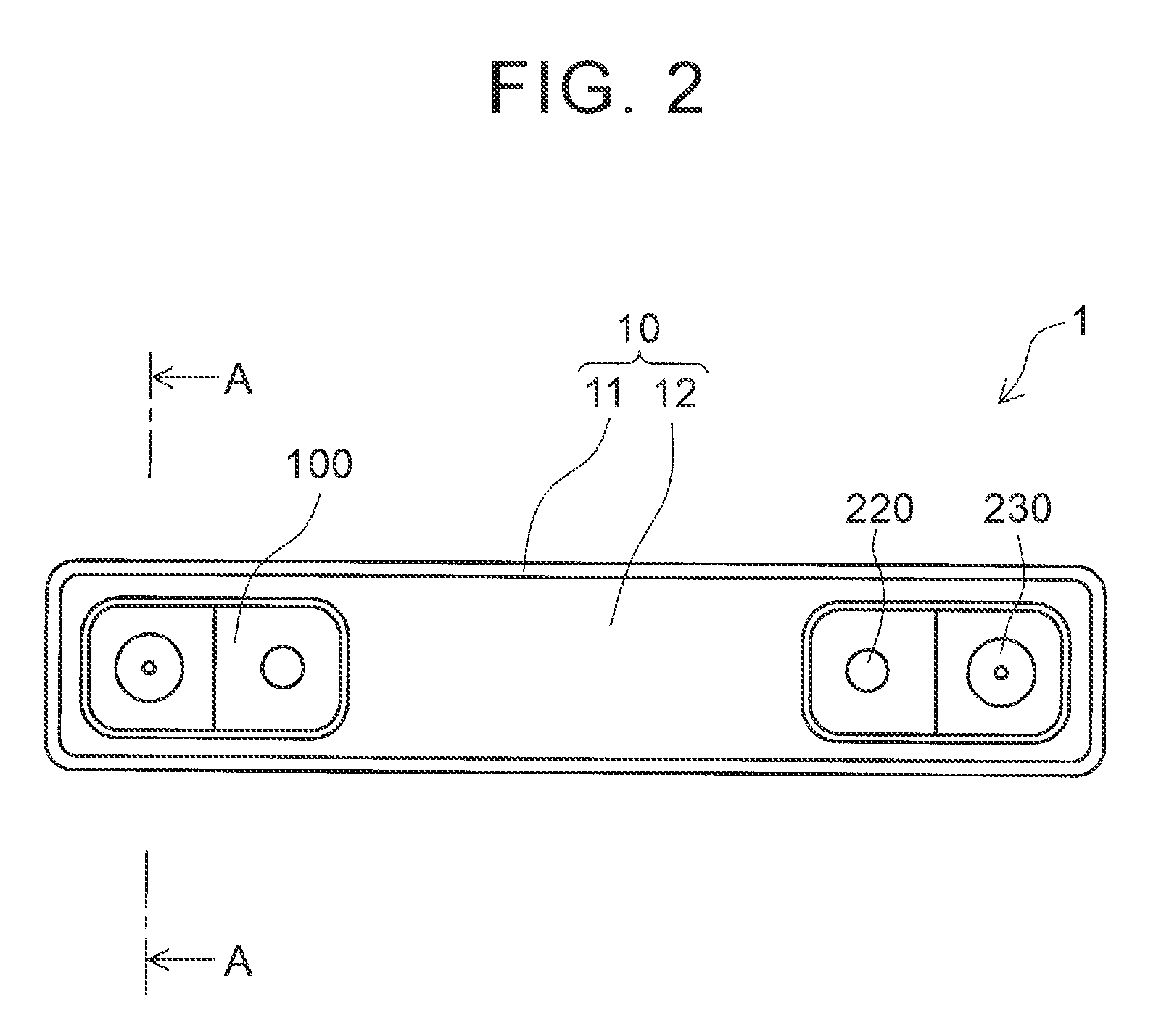
[0039]First, a closed battery produced by a producing method according to the present embodiment will be described. FIG. 1 is a sectional view showing a schematic configuration of a battery 1 of the present embodiment. FIG. 2 shows a plan view of the battery 1.

[0040]The battery 1 of the present embodiment is a lithium ion secondary battery. As shown in FIG. 1 and FIG. 2, the battery 1 includes a battery case 10 made of metal in a flat form. An electrode body 20 and an electrolyte 30 are housed inside the battery case 10. As shown in FIG. 2, the battery case 10 includes a case body 11, a cover 12 covering an opening located at an upper pa...


PUM

PropertyMeasurementUnit
widthaaaaaaaaaa
widthaaaaaaaaaa
widthaaaaaaaaaa

Abstract

During joining, while the inversion plate is inserted in a recessed portion of the connecting member and an opening of the recessed portion faces upward in a vertical direction, a boundary at which an inner wall surface of the recessed portion faces an outer side surface of the inversion plate is continuously radiated with a laser beam from above by one round or more. The inner wall surface in a circular shape of the connecting member is an inclined surface inclined further apart from the outer side surface of the inversion plate as the inclined surface is located closer to the laser beam radiation side, and the inclined surface satisfies w / (h·D)≧0.002 (w: a length of the inclined surface in a radial direction, h: a height of the inclined surface, D: a diameter of the inclined surface on an opposite side to the laser beam radiation side).

Description

INCORPORATION BY REFERENCE[0001]The disclosure of Japanese Patent Application No. 2015-166918 filed on Aug. 26, 2015 including the specification, drawings and abstract is incorporated herein by reference in its entirety.BACKGROUND OF THE INVENTION[0002]1. Field of the Invention[0003]The present invention relates to a producing method of a sealed battery. More specifically, the present invention relates to a producing method of a sealed battery including a current interrupt device (CID) in a battery case.[0004]2. Description of Related Art[0005]Sealed secondary batteries might experience abnormal increase in internal pressure over their normal ranges due to some abnormalities. To cope with this, there have been provided secondary batteries including CIDs that operate at higher internal pressures than normal internal pressures of the secondary batteries.[0006]Some CIDs of secondary batteries include inversion plates made of metal plates each of which has a circular outer shape, and is...

Claims


Application Information

Patent Timeline
Patent Type & Authority Applications(United States)
IPC IPC(8): H01M10/04H01M10/058H01M2/30H01M10/0525H01M2/34H01M2/06H01M50/119H01M50/176
CPCH01M10/049H01M2/345H01M10/058H01M2/30H01M10/0525H01M2/06H01M10/0587H01M50/578H01M50/176H01M50/119Y02E60/10Y02P70/50H01M50/166H01M50/116
Inventor UMEYAMA, HIROYAMURATA, ICHIRO
Owner TOYOTA JIDOSHA KK
Learn More