Link Unit and Method for Producing a Link Unit

a link unit and link technology, applied in the field of link units and methods, can solve the problems of minor damage to the carrier surface, unimportant unbalances on the components to be welded, and to be expected, so as to improve the avoidance of the notch effect, the effect of increasing the manufacturing accuracy and increasing production complexity

Active Publication Date: 2017-03-02
SAF HOLLAND GMBH
View PDF1 Cites 1 Cited by
  • Summary
  • Abstract
  • Description
  • Claims
  • Application Information

AI Technical Summary

Benefits of technology

[0017]In particular, the transition section preferably has a curvature which merges tangentially into the tubular section or into the upset section. Here, tangentially merging is considered to mean, in particular, a rounded surface, that is to say the inner face or the outer face of the upset section, which merges tangentially into the correspondingly adjoining inner face or outer face of the tubular section or the upset section. A curvature with a tangential transition into the respectively adjoining surface of the tubular section of the upset section achieves an optimum minimization of the notch effect in the region of the transition between the transition section and the tubular section and / or the transition section and the upset section.
[0018]The transition section particularly preferably has two curvatures, of which one merges tangentially into the tubular section and the other merges tangentially into the upset section. Although two tangential curvatures are associated with higher production complexity, it can prove advantageous to accept said production complexity, in order to achieve an even more improved avoidance of the notch effect and in this way for it to be possible to achieve the service life of the link unit in the case of the cyclical loads to be expected. In particular, it can be preferred here that the two curvatures which are arranged on the transition section also merge tangentially into one another, with the result that the first curvature runs tangentially with respect to the tubular section and, at its opposite end, runs tangentially with respect to the second curvature, and the second curvature, starting from the tangential transition from the first curvature, merges tangentially into the upset section. It goes without saying that a configuration of this type of the transition section makes substantially higher requirements on the manufacturing accuracy during the reshaping of the carrier in order to form the upset section than would be the case in the configuration of a simple, single curvature in the region of the transition section on either the tubular section or the upset section. Said increased manufacturing complexity can be justified, however, in view, in particular, of the particularly high demands made of the link unit with regard to the transmission of force and, at the same time, low wall thicknesses for weight minimization.
[0019]The outer contour of the upset section is advantageously substantially identical to the outer contour of the tubular section. Here, furthermore, the outer contour of the upset section is preferably oriented substantially concentrically with respect to the outer contour of the tubular section. In particular, in the preferred case where both the outer contour of the tubular section and the outer contour of the upset section are of cylindrical configuration, they have the same external diameter in said preferred embodiment. The advantage of said preferred embodiment is that the outer face of the link unit which is constructed from the carrier and the node element can be finished or polished and ground particularly simply in this way and therefore provides few attack points for corrosive media.
[0020]As an alternative, the inner contour of the upset section is preferably substantially identical to the inner contour of the tubular section. In other words, the alternative to the identical configuration of the outer contour of the tubular section and the upset section means that the wall thickness increase in the region of the upset section runs toward the outside. By way of said preferred embodiment, the geometrical moment of inertia with respect to bending can be increased locally, since the mean diameter of the upset section which is decisive for the calculation of the geometrical moment of inertia is higher than the mean diameter of the tubular section. In particular, a relatively thin tube can be adapted in this way to a contact area of the node element with a greater extent along the plane, in which the carrier is joined to the node element.
[0021]In a further preferred embodiment, the node element has a wall thickness in the region of its attachment to the connecting section, which wall thickness is in a ratio of from 0.75 to 1.5 to the wall thickness of the upset section. For the case, in particular, where, in order to increase the variability of the use of a carrier according to the invention, said carrier is fixed to node elements which are designed with different sizes or thicknesses, it is advantageous that the wall thickness difference between the node element and the corresponding upset section of the carrier does not exceed or undershoot a ratio of from 0.75 to 1.5. It has been shown within the context of the present invention that the notch effect to be expected can be kept within limits only within said ratio range, and therefore the service life of the connecting region between the node element and the carrier or upset section is increased. Nevertheless, it can prove advantageous to accept a certain difference between the wall thickness of the node element in the region of its attachment to the connecting section and the wall thickness of the upset section of the carrier and to make provision from the outset within the context of the present invention to permit high variability and capability of combination of different node elements with different carriers and thus to drastically reduce the overall manufacturing and production costs of link units of different size for different commercial vehicles.
[0022]The upset section preferably has an upset extent which is in a ratio of from 0.3 to 2.3, preferably from 0.5 to 1.8 and particularly preferably approximately from 0.7 to 1.6 to a transition extent of the transition section. Adhering to the preferred range of from 0.3 to 2.3 ensures that the upset section is configured in such a way that sufficient material is provided for melting the carrier in the region of the upset section which is partially removed during the use of the rotary friction welding method, an increase in weight being avoided at the same time, by the length of the transition region being adapted proportionally to the upset extent. By the transition extent being kept to be not shorter than 0.3 times the upset extent, a sufficient safety factor is additionally advantageously present in the case of a complete removal of the upset section, it being possible for the transition section to serve on its side with the greater wall thickness for fixing the node element. It has been determined that high safety against complete consumption of the upset section with, at the same time, only a small weight increase can be achieved by way of the preferred ratio range of from 0.5 to 1.8. By a preferred range of from 0.7 to 1.6 being selected, the link unit can be adapted in a particularly satisfactory manner to the requirements which prevail in heavy duty commercial vehicles, since a particularly satisfactory ratio of the strength of the connection between the carrier and the node element and, at the same time, an only low weight of the link unit, in particular as a result of the only small length of the transition section.

Problems solved by technology

In addition, only minor damage of the surfaces of the carrier is to be expected in the case of hydroforming.
Unbalances on the components to be welded are without significance for said vibration friction welding method.

Method used


Image

  • Link Unit and Method for Producing a Link Unit
  • Link Unit and Method for Producing a Link Unit
  • Link Unit and Method for Producing a Link Unit

Examples


Embodiment Construction

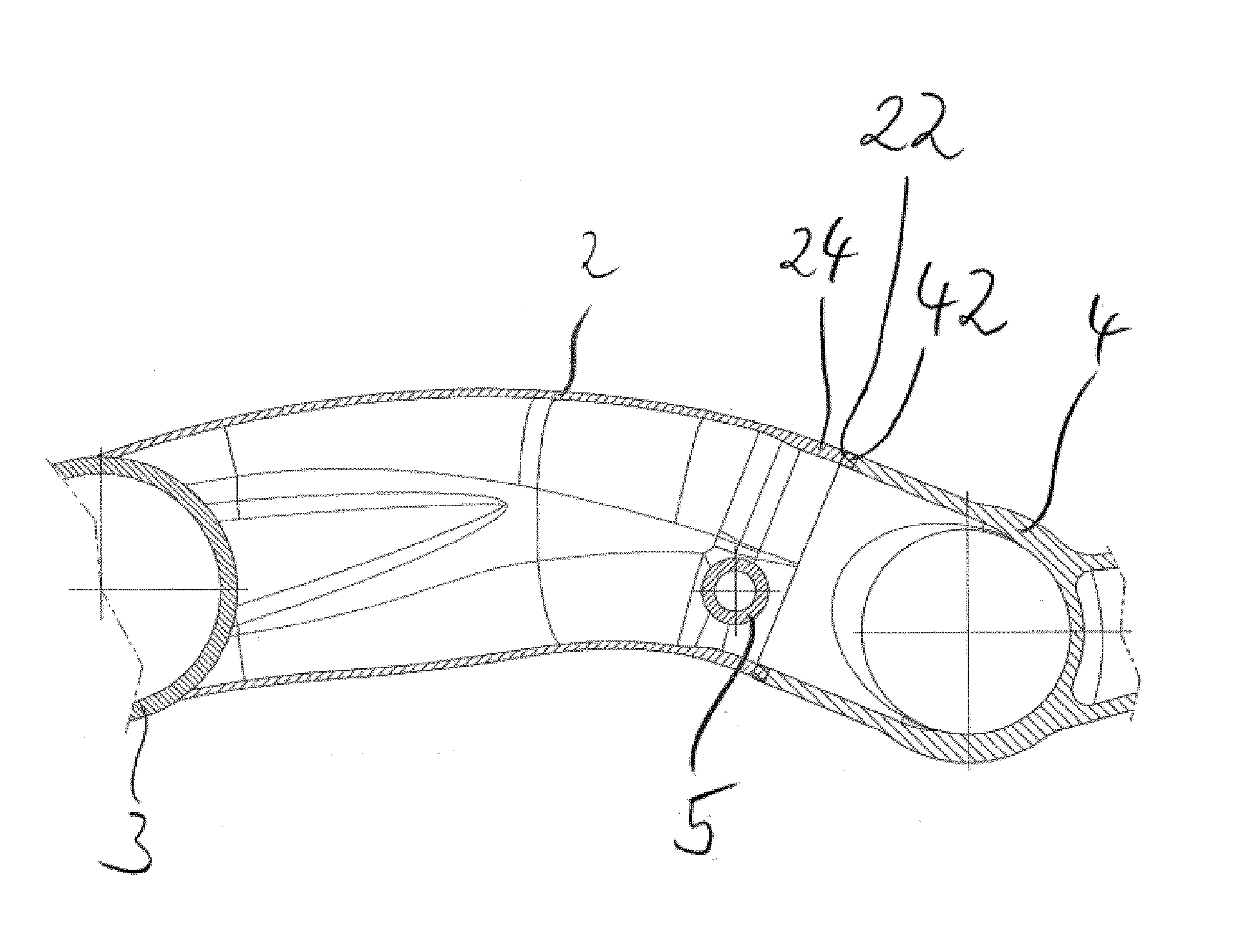
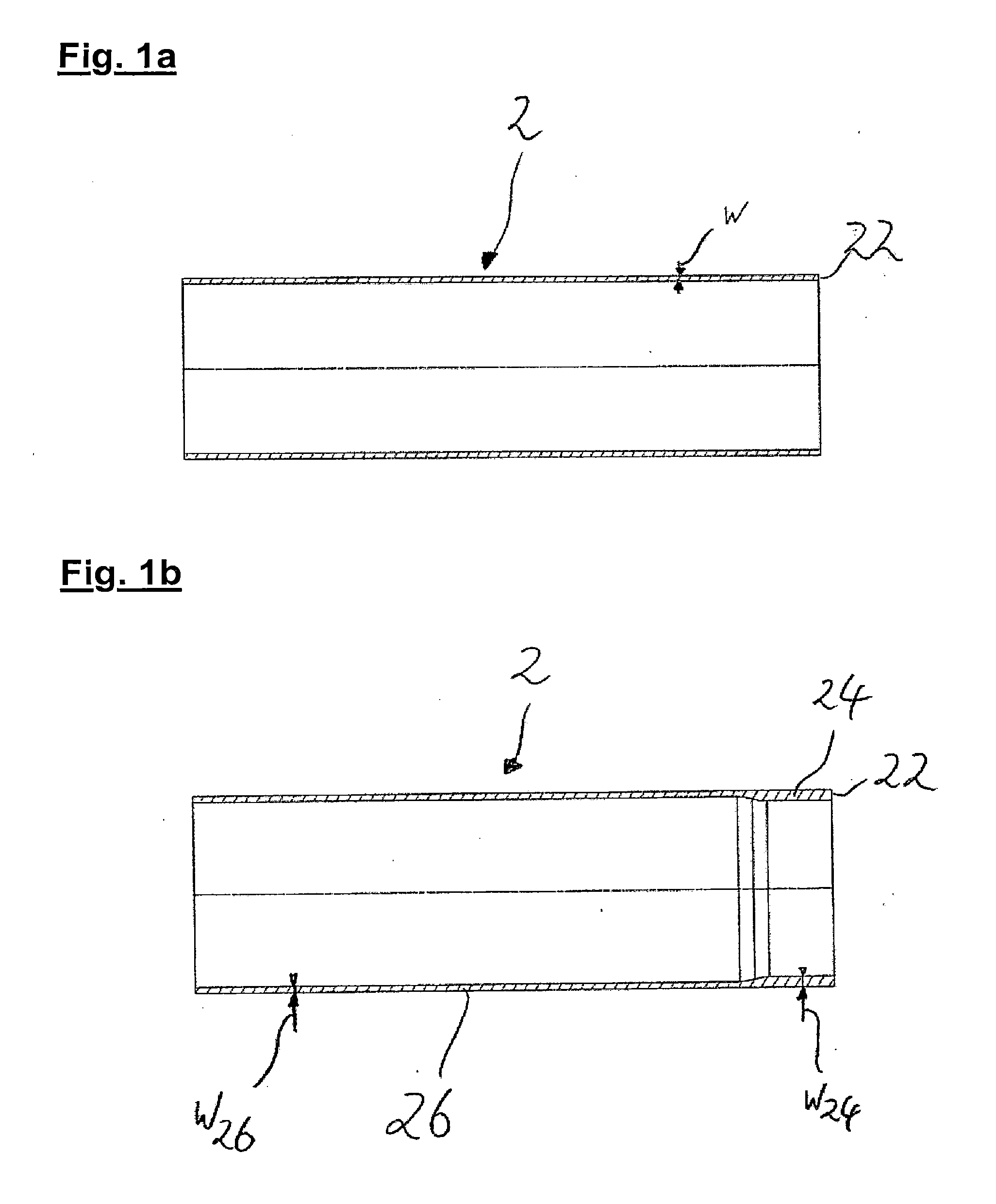
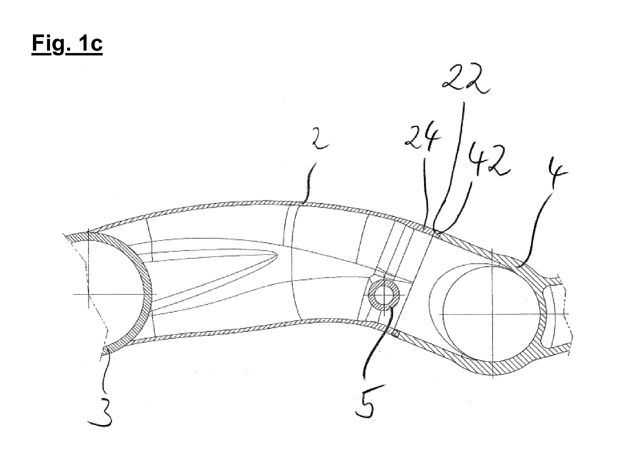
[0028]FIG. 1a shows the first step of the method for producing a link unit, a carrier 2 which is preferably configured as a simple tube and has a substantially constant wall thickness w. In particular, it is preferred that, before the beginning of the method, the carrier 2 is a straight cylindrical tube which extends in a rotationally symmetrical manner with respect to a cylinder axis which is shown in the figure. FIG. 1b shows one preferred embodiment of the carrier 2 after the reshaping method has been carried out, an upset section 24 being formed on the right-hand side of the carrier 2 in the figure, which upset section 24 has a higher wall thickness w24 than the wall thickness of the remaining regions of the carrier 2. Here, the non-deformed or non-upset region of the carrier 2 is preferably defined as a tubular section 26 which has a wall thickness w26 which is preferably equal to the wall thickness w of the non-processed carrier 2 which is shown in FIG. 1a. FIG. 1c shows the p...


PUM

PropertyMeasurementUnit
thicknessaaaaaaaaaa
structure strengthaaaaaaaaaa
mean wall thicknessaaaaaaaaaa

Abstract

The present invention relates to a method for producing a link unit, comprising the steps of provision of a carrier, reshaping of the carrier in the region of a first connecting section in such a way that an upset section is formed, the wall thickness of the carrier being increased in the region of the upset section, and provision of a node element with a joint section, and connecting of the joint section to the first connecting section by means of a rotary friction welding method. Furthermore, the invention relates to a link unit, in which a carrier which is configured in the manner of a hollow body is connected to a node element by means of a rotary friction welding method.

Description

BACKGROUND OF THE INVENTION[0001]The present invention relates to a method for producing a link unit, and to a link unit, in particular for use in commercial vehicles.[0002]Link units of this type and methods for producing them are already known from the prior art. Thus, in particular in commercial vehicle chassis, the axles or axle stub arrangements are mounted by means of longitudinal links which are suspended pivotably on the frame of the vehicle, spring elements and torsional damper elements at the same time acting on the longitudinal links and ensuring controlled displaceability of the wheels of the commercial vehicle which are arranged on the chassis. Here, the longitudinal links which are known from the prior art are frequently configured as cast parts, more or fewer additional components of the link or components to be connected to the link being configured in one piece with the longitudinal link. In the case of said links which are configured as a cast part, the high weight...

Claims


Application Information

Patent Timeline
Patent Type & Authority Applications(United States)
IPC IPC(8): B60G7/00B23K20/12B21D53/88B60G9/00
CPCB60G7/001B60G9/003B23K20/129B21D53/88B23K2201/006B60G2200/31B60G2204/4302B60G2206/32B60G2206/82013B60G2206/81B60G2206/11B23K2101/006
Inventor DREWES, OLAFBIEWER, FREDERIK
Owner SAF HOLLAND GMBH
Why Eureka
Try Eureka