
Joint sleeve for high temperature insulated bus pipes

a high temperature insulation and bus pipe technology, applied in the direction of butt joining bus-bars, connection contact material, electrical equipment, etc., can solve the problems of poor fire resistance of the joint sleeves, and the known joint sleeves do not meet the new requirements of safety and reliability applicable to power consuming facilities in hazardous environments

Active Publication Date: 2017-02-16
DANIELIAN NIKOLAI +1
View PDF0 Cites 9 Cited by
  • Summary
  • Abstract
  • Description
  • Claims
  • Application Information

AI Technical Summary

Benefits of technology

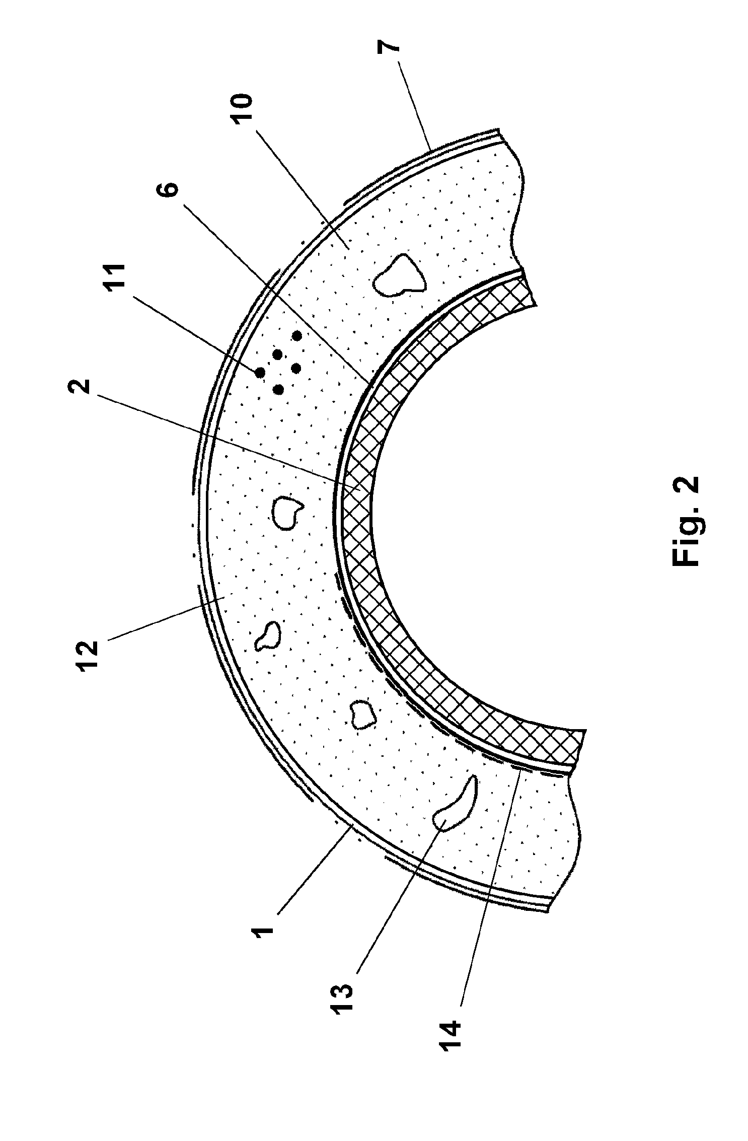
The patent is about a joint sleeve for high temperature bus pipes used in power consuming facilities in hazardous environments. The joint sleeve has an improved fire resistance compared to previous versions. It consists of a case made of non-magnetic metal with a fire-resistant coating, containing an insulated supporting tube with connectable contacts of the busbar sections. The case is covered with an outer fire-resistant coating and a grounding screen made of non-magnetic metal. A composite fire-resistant layer made of a filler capable of thermal expansion upon heating and a binder is placed between the case and the grounding screen, which adjoins the outer surface of the case and the inner surface of the grounding screen. The fire-resistant layer acts as insulation and is formed by the filler and binder during the thermal expansion. The binder can be epoxy resin combined with a curing agent and the filler can be thermally expandable graphite or powder graphite. The joint sleeve provides better protection against fire exposure and meets safety and reliability requirements for power consuming facilities in hazardous environments.

Problems solved by technology

It was proved in practice that the known joint sleeves manufactured according to Patent RU2439764C1 are durable and fire resistant within some limits of thermal load, however the known joint sleeves do not comply adequately with new requirements of safety and reliability applicable to power consuming facilities in hazardous environments.
This is due to poor fire resistance of the joint sleeves under long thermal exposure including exposure to direct flame.

Method used


Image

  • Joint sleeve for high temperature insulated bus pipes
  • Joint sleeve for high temperature insulated bus pipes
  • Joint sleeve for high temperature insulated bus pipes

Examples


Embodiment Construction

[0025]While the invention may be susceptible to embodiment in different forms, there are described in detail herein below, specific embodiments of the present invention, with the understanding that the present disclosure is to be considered an exemplification of the principles of the invention, and is not intended to limit the invention to that as illustrated and described herein.

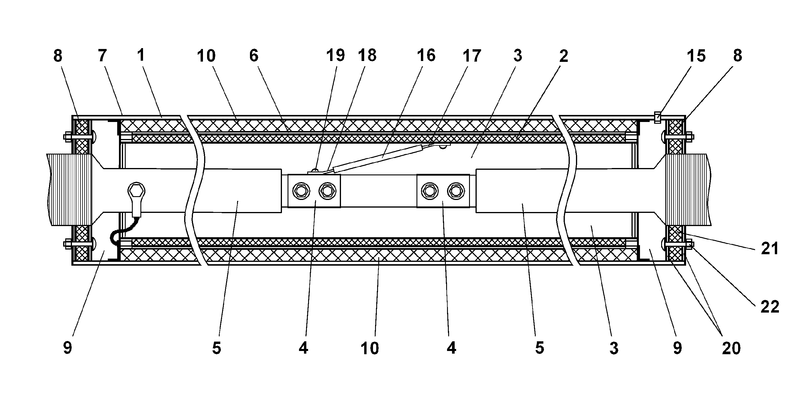
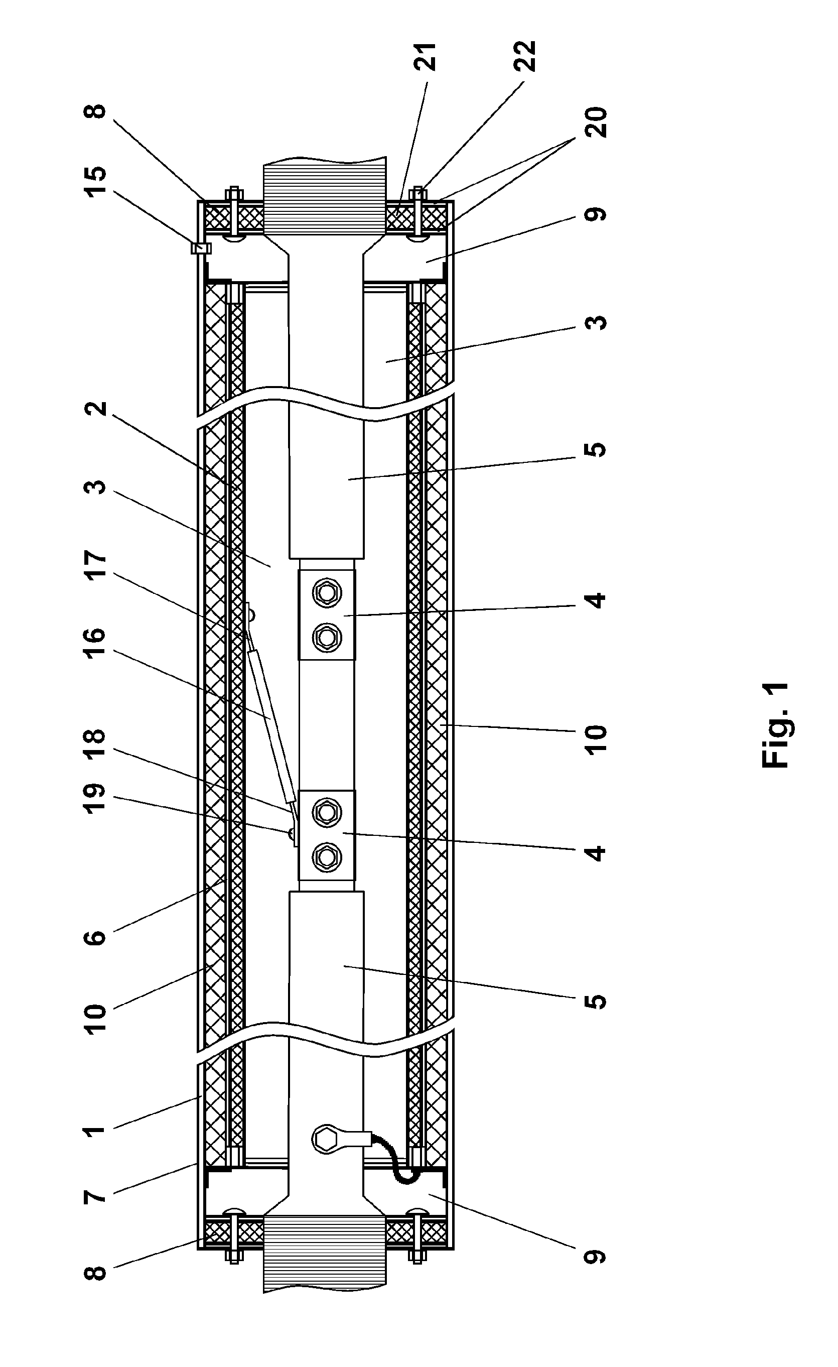
[0026]According to the first inventive embodiment of a joint sleeve (FIG. 1) for coupling at least two busbar sections (particularly, HTIBP) of a busbar, the joint sleeve comprises a case 1, defining butt ends, end hollows 9 adjacent with the butt ends; the case 1 encloses an electrically insulated supporting tube 2 containing a chamber 3 inside thereof. The chamber 3 encloses contacts 4 of busbar sections 5. The supporting tube 2 is made of paper impregnated with a binder.

[0027]The joint sleeve comprises a grounding screen 6 affixed to the outside surface of the supporting tube 2. The supporting tube 2 is ...


PUM


Abstract

A joint sleeve is proposed for connecting busbar sections, each having connectable contacts. In an embodiment, the sleeve includes—a non-magnetic case defining butt ends occluded with non-magnetic flanges each having a hole securing the respective busbar section therein,—a fire-resistant coating covering the case,—an electrically insulated supporting tube disposed within the case and defining a chamber therein, enclosing the connectable contacts,—a grounding screen mounted on the supporting tube, and—a fire-resistant layer disposed between the case and the screen capable of thermal expansion upon heating thereof, thereby improving fire-resistance. Instead of the fire-resistant layer, another embodiment includes an annular air chamber formed between the case and the supporting tube, while the annular chamber is in communication with hollows, and the supporting tube is closed by another pair of flanges with holes securing the respective busbar sections. The sleeve allows for improving fire-safety of power consuming facilities.

Description

CROSS-REFERENCE TO RELATED APPLICATION[0001]This U.S. patent application claims priority under 35 U.S.C. 119 (a) through (d) from a Russian patent application RU 2015133962 filed on 13 Aug. 2015, hereby entirely incorporated by reference.FIELD OF THE INVENTION[0002]The invention relates to means for transmitting electrical energy from power supplies to power consuming facilities, in particular, it relates to parts of power distribution systems such as joint sleeves for assembling busbar sections, specifically high temperature insulated bus pipes. The invention is to be used in the field of electrical engineering.BACKGROUND OF THE INVENTION[0003]There is known a busbar joint sleeve that includes a tubular case whose butt ends are closed with plates disposed outside the case. The plates have central openings, in which busbars are located, and the case has a chamber receiving contacts of the bars to be connected (Busbar joint sleeves, 35 kV phase-insulated busbar wireway, RAUTA-ENERGO)...

Claims


Application Information

Patent Timeline
IPC IPC(8): H02G5/06H01R4/60H01R4/70
CPCH02G5/06H01R4/60H01R4/70H01R4/643H02G5/007H02G5/08
Inventor DANIELIAN, NIKOLAIYASHINA, FATIMA FERKHATOVNAGALSTYAN, GAGIK GAMLETOVICH
Owner DANIELIAN NIKOLAI
Learn More