Method of detecting the position of a lateral canal extending from a root canal to a periodontal space, and detecting an opening direction of the lateral canal, apparatus for the same, and a computer readable storage medium storing program to have a computer execute the method

a technology of lateral canal and position, which is applied in the field of detecting the position of lateral canal, can solve the problems of affecting the accuracy of lateral canal detection, the error of the distance display, and the inability to improve symptoms, etc., and achieves the effect of higher accuracy and improved accuracy

Active Publication Date: 2017-02-16
TOEI ELECTRIC
View PDF9 Cites 5 Cited by
  • Summary
  • Abstract
  • Description
  • Claims
  • Application Information

AI Technical Summary

Benefits of technology

[0019]According to one embodiment of the present invention, it is possible to detect a position of a lateral canal with higher accuracy. Additionally, according to one embodiment of the present invention, it is possible to detect an opening direction of a lateral canal with higher accuracy.

Problems solved by technology

When a focus of disease lies in not only a root apex but also a root side, such a case occurs that an improvement of symptoms cannot be expected unless an operator conducts treatment while being aware of a lateral canal “e”.
However, depending on the position of the measurement electrode in the root canal, there may be an error between the distance display shown on the display section as a result of this detection of a lateral canal position and the actual lateral canal position.
The error is due to differences among the signals measured at different positions of the measurement electrode in the root canal.
However, if the opening direction is detected by the above-described two steps, the position of the measurement electrode for detecting a lateral canal direction in the root canal has been a cause for an error.
For example, the measurement electrode for detecting a lateral canal direction vertically moves and rotates in the root canal; thus, a change in the position of the lateral canal and the opening portion of the measurement electrode for detecting a lateral canal direction in the long axis rotation direction, and a change in a measured signal value have been a cause for an error in an angle indicating the opening direction of the lateral canal.
Particularly, it was difficult for an operator to rotate the measurement electrode for detecting a lateral canal direction 360 degree in one action, and to accurately detect the opening direction of the lateral canal.

Method used


Image

  • Method of detecting the position of a lateral canal extending from a root canal to a periodontal space, and detecting an opening direction of the lateral canal, apparatus for the same, and a computer readable storage medium storing program to have a computer execute the method
  • Method of detecting the position of a lateral canal extending from a root canal to a periodontal space, and detecting an opening direction of the lateral canal, apparatus for the same, and a computer readable storage medium storing program to have a computer execute the method
  • Method of detecting the position of a lateral canal extending from a root canal to a periodontal space, and detecting an opening direction of the lateral canal, apparatus for the same, and a computer readable storage medium storing program to have a computer execute the method

Examples


first embodiment

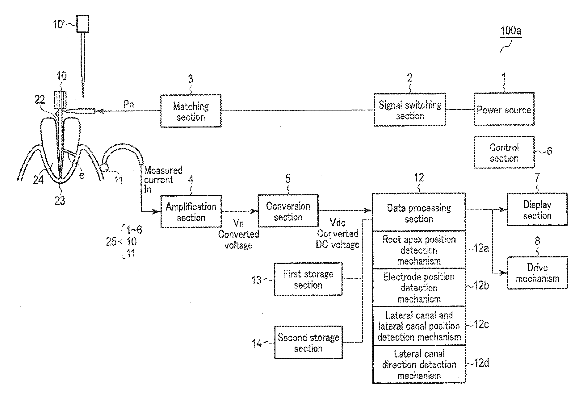
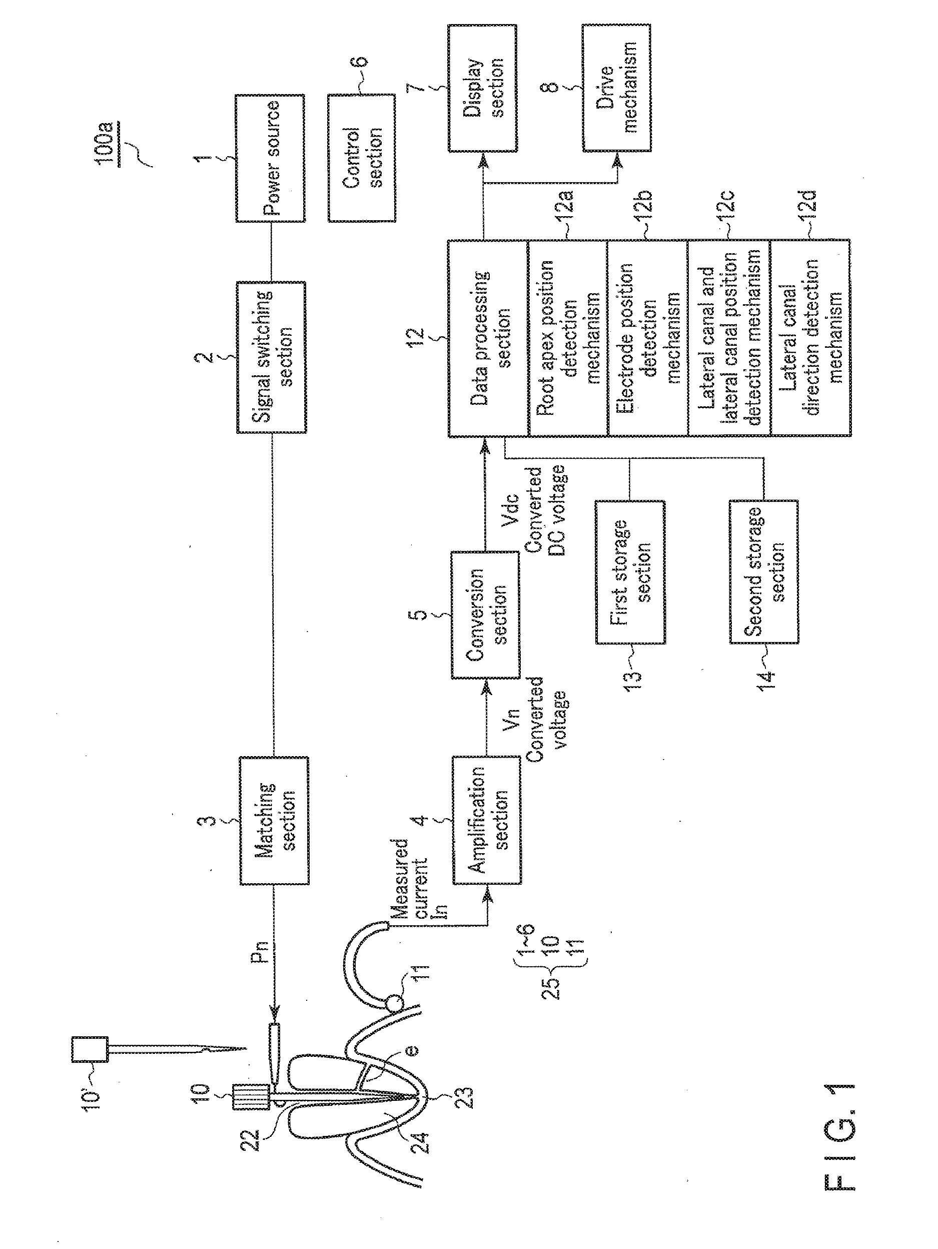
[0037]FIG. 1 shows the lateral canal detection apparatus 100a according to the present invention.

[0038]In FIG. 1, reference numeral 1 denotes a power source which outputs signals Pn used for measurement having one or a plurality of different frequencies. The power source 1 outputs signals Pn used for measurement at two frequencies, for example, 500 Hz and 2 kHz. Reference numeral 2 denotes a signal switching section, which selects either one of signals Pn of 500 Hz or 2 kHz, or performs switching between the signals to sequentially feed signals to a matching section 3 according to an instruction from a control section 6. The matching section 3 converts the signals Pn to be fed to the measurement electrode 10 for detecting a root apex position and a lateral canal position (hereinafter, referred to as “electrode for position detection”) into voltages suitable for measurement, and feeds them to an amplification section 4. The amplification section 4 converts and amplifies measured curr...

second embodiment

[0087]The lateral canal detection apparatus 100b of the second embodiment will be described with reference to FIG. 11. The apparatus shown inFIG. 11 is the same as the apparatus shown in FIG. 1, except for the electrode holding mechanism 15 for holding the electrode 10′ for direction detection. The descriptions of the functions that are the same as those of the apparatus shown in FIG. 1 are omitted. In the following, the function of detecting an opening direction of a lateral canal using the electrode 10′ for direction detection is described.

[0088]The lateral canal detection apparatus 100b shown in FIG. 11 is provided with an electrode holding mechanism 15 for holding the electrode 10′. An example of the electrode holding mechanism 15 is shown in FIG. 12. The electrode holding mechanism 15 is provided with a holding section 15a which holds the electrode 10′, and a rotation mechanism 15b which transmits rotation to the holding section 15a. By rotating the rotation mechanism 15a, the ...


PUM


Abstract

A method comprising: comparing each value of measured signals with a plurality of model tooth position measurement data groups, and storing the measured signal values and an indication value at the time when a fluctuation of the indication value which indicates a distance from a root apex position to a distal end of an electrode for position detection shows an apex in a convex shape, the indication value being indicated by a model tooth position measurement data group in a predetermined relationship; and comparing second-time measured signal values and an indication value with the stored first-time measured signal values and the stored indication value, respectively, if at least two of them correspond or fall within a predetermined error range, stopping the electrode and measuring a position of the distal end of the electrode.

Description

CROSS-REFERENCE TO RELATED APPLICATION[0001]This application is based upon and claims the benefit of priority from the prior Japanese Patent Application No. 2015-159005, filed Aug. 11, 2015, the entire contents of which are incorporated herein by reference.BACKGROUND OF THE INVENTION[0002]1. Field of the Invention[0003]The present invention relates to a method of detecting a position of a lateral canal extending from a root canal (hereinafter, referred to as “lateral canal”) to a periodontal space direction and detecting an opening direction of the lateral canal, an apparatus for the same, and a computer readable storage medium storing a program to have a computer execute the method, during diagnosis or treatment in dentistry. Hereinafter, “lateral canal position” refers to a position of a lateral canal in the long axis direction in a root canal, and “opening direction of lateral canal” refers to a position of a lateral canal in the rotation direction of the long axis in a root cana...

Claims


Application Information

Patent Timeline
Patent Type & Authority Applications(United States)
IPC IPC(8): A61C19/04A61C5/02A61B5/06A61B5/053A61B5/00
CPCA61C19/042A61C19/041A61B5/0534A61B5/682A61B2562/0209A61B5/063A61B5/742A61C5/02A61B5/7246A61C5/40
Inventor OTSUKA, MASAHIRO
Owner TOEI ELECTRIC
Why Eureka
Try Eureka