
Capacitive voltage sensor for medium voltage metering

Active Publication Date: 2017-02-09
SCHNEIDER ELECTRIC USA INC
View PDF0 Cites 24 Cited by
  • Summary
  • Abstract
  • Description
  • Claims
  • Application Information

AI Technical Summary

Benefits of technology

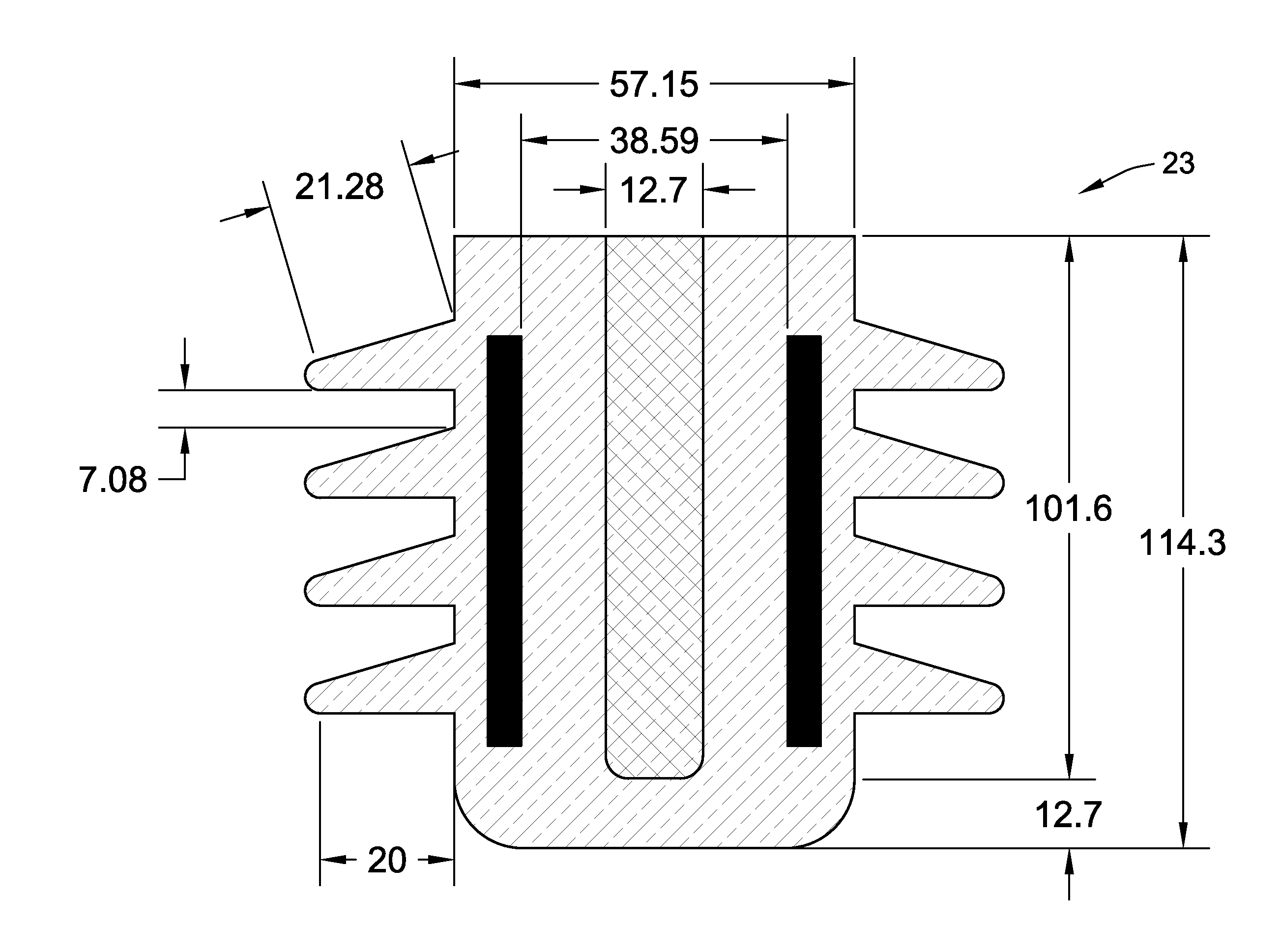
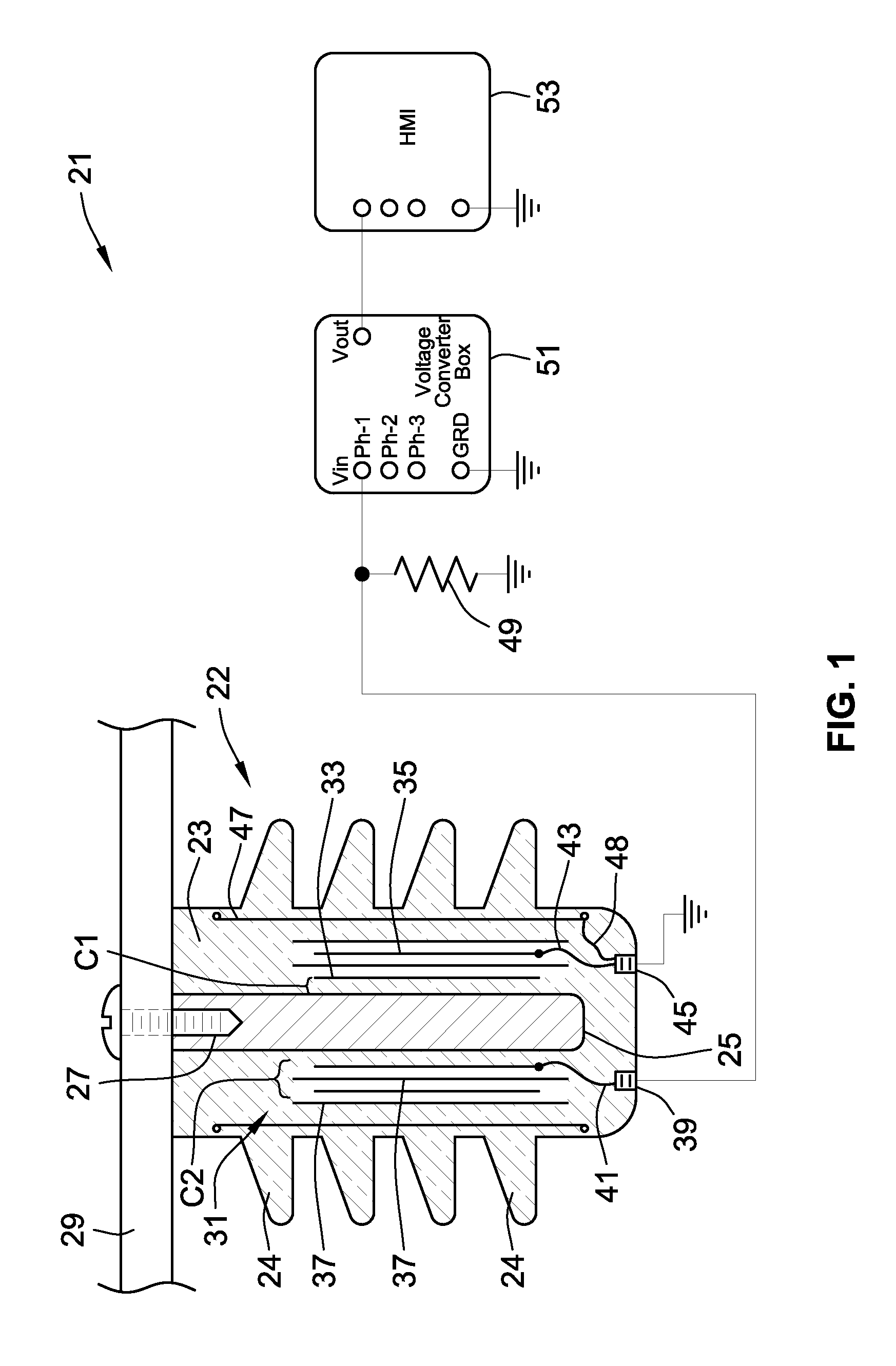
The present invention provides a compact design for a voltage transformer that eliminates the effects of ambient conditions and reduces the cost compared to traditional VTs. The design includes two cylindrical capacitors of different values embedded within a dielectric resin, forming a capacitive voltage divider. The addition of a parallel precision resistor on the secondary will damp transients and increase the transformation ratio. The transformation ratio is only dependent on the geometric construction of the capacitors, making it possible to create a very accurate sensing device. The device can be used for practical MV metering functions at reasonable cost. The design also incorporates electromagnetic shielding to eliminate the electromagnetic effects of any electrical source different from the one being measured. The CVT has advantages such as reduced measurement sensitivity to ambient temperature and humidity, a compact design, reduced overall cost, being lighter, easier to manufacture and install, and with higher capacitance values embedded in a small space making electronic signal processing easier with less circuit loading.

Problems solved by technology

Known approaches to metering sensors in MV switchgear include using traditional magnetic core Voltage Transformers (VTs) which use electromagnetic induction but suffer from high weight, expense, and large space requirements and are limited in the voltage they can read because of the saturation of their ferromagnetic core.
Resistive divider technology can also be used but suffers from measurement accuracy concerns at higher voltages due to e.g. Johnson-Nyquist noise, thermocouple effects, and susceptibility to parasitic capacitances.
However, the known transformers for metering MV are large, e.g. several meters high, and expensive.
Further, known capacitive voltage dividers may have accuracy problems due to the variation of capacitance values caused by changes in ambient conditions such as temperature and humidity.
Capacitive voltage transformers for voltage presence indication, such as U.S. Pat. No. 8,395,397 to Handshoe et al., are small but possess little accuracy.

Method used


Image

  • Capacitive voltage sensor for medium voltage metering
  • Capacitive voltage sensor for medium voltage metering
  • Capacitive voltage sensor for medium voltage metering

Examples


Embodiment Construction

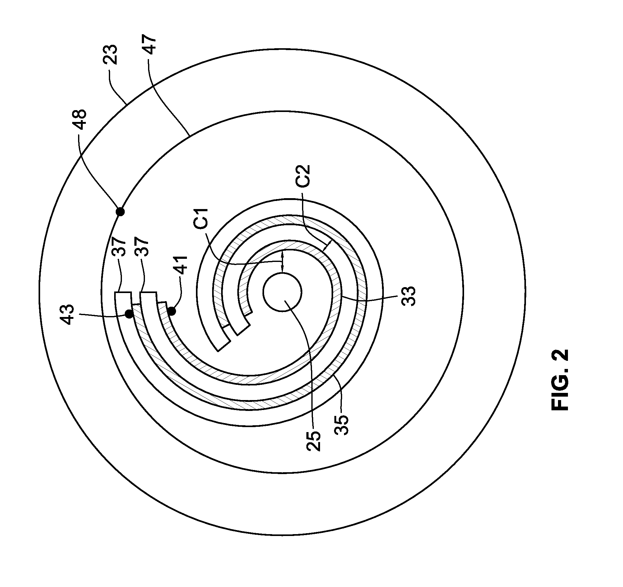
[0007]The present invention addresses these needs by providing a compact design where the two capacitors required for voltage transformation are embedded in a single dielectric encapsulation cast in an optimized geometrical configuration where the effect of ambient conditions on accuracy is strongly diminished, thus supporting practical MV metering functions at reasonable cost. Two cylindrical capacitors of different values are embedded within a dielectric resin to form a capacitive voltage divider. Addition of a parallel precision resistor on the secondary will damp transients and increase the transformation ratio. The divider will provide an output voltage proportional to the input voltage, thus creating an Capacitive Voltage Transformer.

[0008]Two cylindrical capacitors of different values are formed within a dielectric resin to create a capacitive voltage divider. When two capacitors connected in series are subjected to the same temperature and made of the same material, the perm...


PUM


Abstract

Two cylindrical capacitors of different values are created in series within a single dielectric resin body to form a capacitive voltage divider for a Medium Voltage sensor. By eliminating temperature variance both capacitors' permittivity is the same, and consistent measurements may be achieved. A first capacitor in the picofarad capacitance range is formed by a rod-shaped central primary conductor, one layer of a wrapped foil capacitor as a second conductor, and the resin body as a dielectric. The wrapped foil capacitor provides a second capacitor in the nanofarad capacitance range and is also embedded within the resin body. The resin body provides a dielectric material almost impervious to ambient changes in operating range and allows for a compact design. A precision resistor can be added in parallel to the first and second capacitors to damp transients and increase the transformation ratio.

Description

FIELD OF THE INVENTION[0001]The present invention is related to capacitive voltage transformers (CVTs), also known as capacitive voltage dividers, and especially to CVTs useful for metering applications in medium voltage (MV) environments.BACKGROUND OF THE INVENTION[0002]Smart power grids require large quantities of current and voltage metering sensors to track power flows, to get a voltage proportional to the one being measured, and take intelligent actions.[0003]Known approaches to metering sensors in MV switchgear include using traditional magnetic core Voltage Transformers (VTs) which use electromagnetic induction but suffer from high weight, expense, and large space requirements and are limited in the voltage they can read because of the saturation of their ferromagnetic core.[0004]Resistive divider technology can also be used but suffers from measurement accuracy concerns at higher voltages due to e.g. Johnson-Nyquist noise, thermocouple effects, and susceptibility to parasiti...

Claims


Application Information

Patent Timeline
IPC IPC(8): G01R15/18G01R19/00
CPCG01R19/0084G01R15/18G01R15/16
Inventor BARBA JIMENEZ, EDUARDO
Owner SCHNEIDER ELECTRIC USA INC
Learn More