Eureka AIR delivers breakthrough ideas for toughest innovation challenges, trusted by R&D personnel around the world.

Lighting device for a motor vehicle headlight

a headlight and motor vehicle technology, applied in the field of lighting devices, can solve the problems of preventing continuity, unattractive appearance, and relatively unattractive appearance, and achieve the effect of occupying little spa

Active Publication Date: 2017-02-02
VALEO VISION SA
View PDF4 Cites 9 Cited by
  • Summary
  • Abstract
  • Description
  • Claims
  • Application Information

AI Technical Summary

Benefits of technology

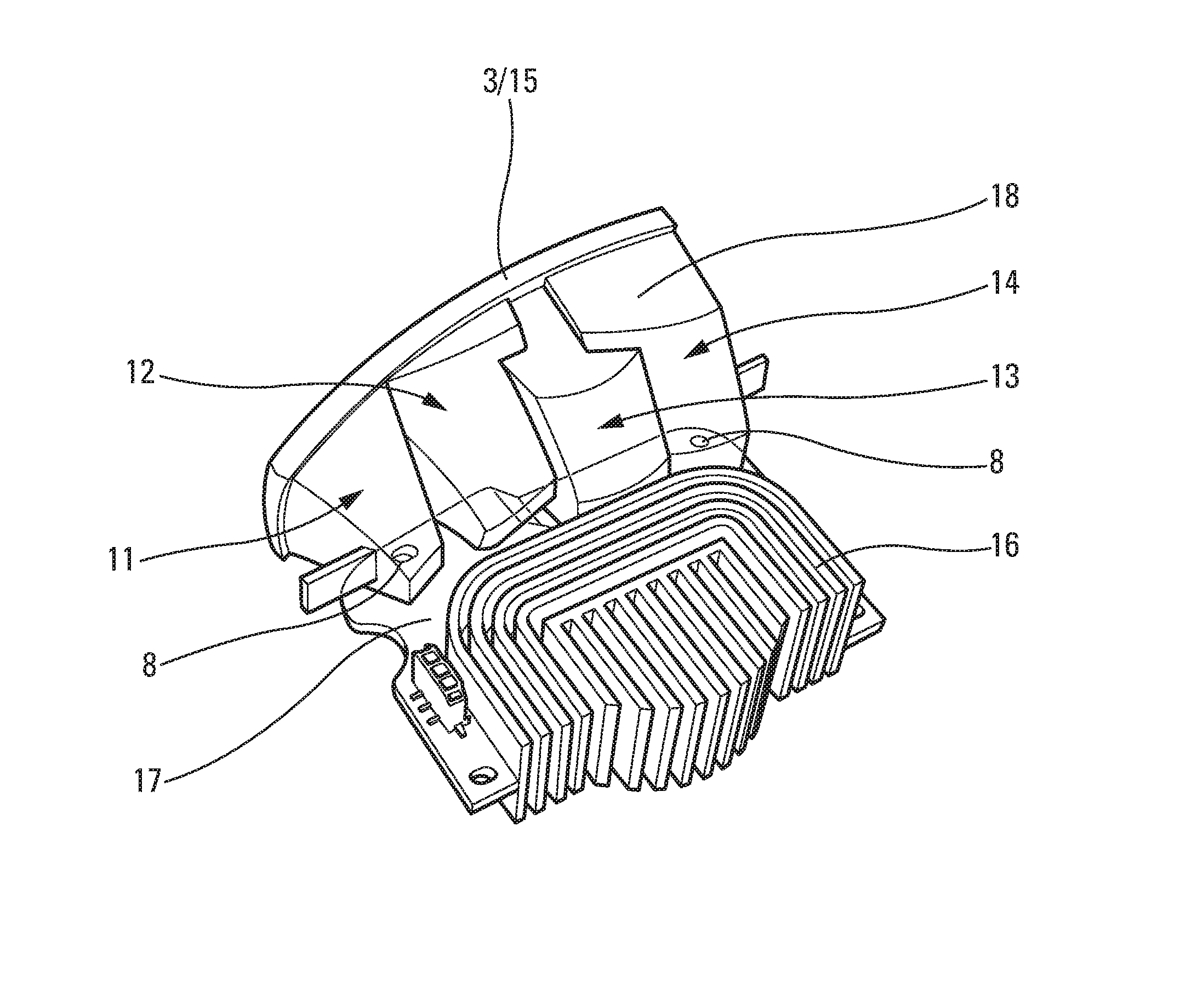
The lighting device creates one or more beams that go towards the horizon, with a specific cut-off profile. It has a single, curved output surface that can be seen through the outer lens of a headlight. This design has the advantage of using a single output surface with multiple light sources that can provide specific lighting functions. The device can produce a variety of light beams based on the needs and requirements of the customer. The guides' lateral walls may be coated with aluminum to efficiently reflect the light beams towards the output face of the guide.

Problems solved by technology

The drawback of this device lies in the shape of the output face of the guide, which is unattractive in appearance.
The use of a plurality of cylindrical output faces results in a relatively unattractive appearance and prevents the preservation of the continuity of curvature of the outer lens located opposite these faces.

Method used


Image

  • Lighting device for a motor vehicle headlight
  • Lighting device for a motor vehicle headlight
  • Lighting device for a motor vehicle headlight

Examples


Embodiment Construction

[0071]The terms “vertical” and “horizontal” are used in the present description to denote directions, notably beam cut-off directions, having an orientation perpendicular to the plane of the horizon for the term “vertical”, and having an orientation parallel to the plane of the horizon for the term “horizontal”. They are to be considered in the conditions of operation of the device in a vehicle. The use of these words does not mean that small variations around the vertical and horizontal directions are excluded from the invention. For example, an inclination of about + or −10° relative to these directions is considered here as a minor variation around the two predominant directions.

[0072]Similarly, throughout the present text, the terms “front” and “rear” are to be interpreted in relation to the direction of propagation of the light emerging from the lighting device toward the front.

[0073]The term “parallel” or the concept of coincident axes is to be interpreted here, notably, as su...


PUM


Abstract

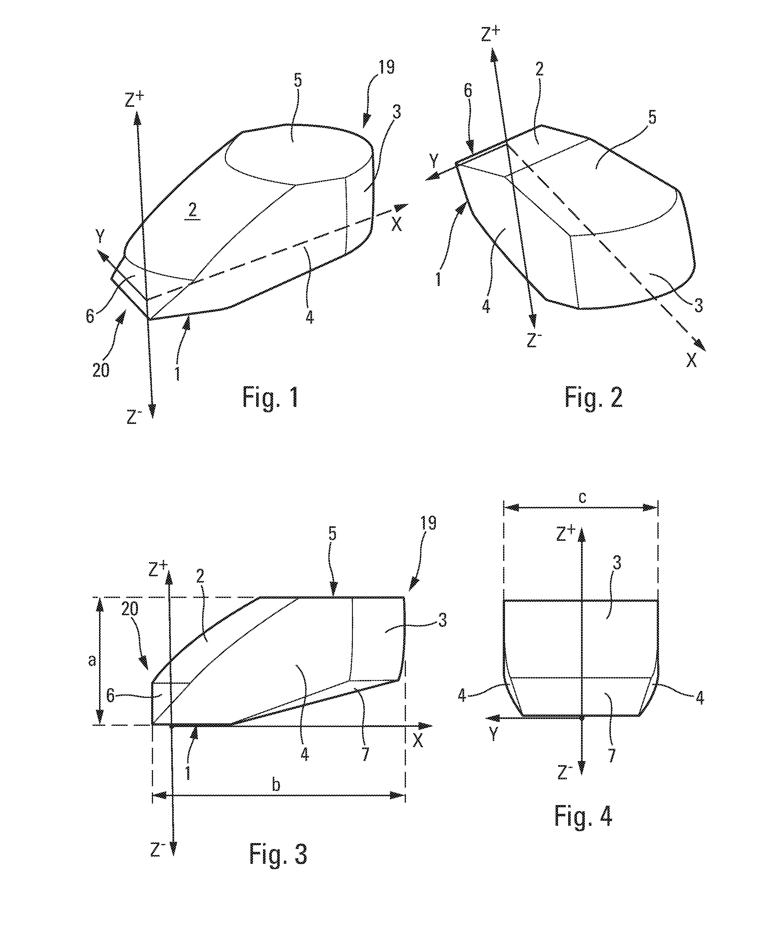
A lighting device, notably for a motor vehicle, comprising at least one module having an optical axis O, each module having:a light source configured to emit a light beam in an overall direction substantially forming a secant to the optical axis O anda light orientation guide adapted to direct the light beam emitted by the light source in a manner substantially parallel to said optical axis O at the output of said the light orientation guide and adapted to form a cut-off in the light beam.The lighting device comprises a single portion for the output of the light beam, the output surface of which is continuously curved and is common to all the modules.

Description

CROSS-REFERENCE TO RELATED APPLICATIONS[0001]This application claims priority to the French application 1557183, filed Jul. 28, 2015, which application is incorporated herein by reference and made a part hereof.BACKGROUND OF THE INVENTION[0002]1. Field of the Invention[0003]The present invention relates to a lighting device.[0004]A preferred application relates to the motor vehicle industry for the production of signaling and / or lighting devices, notably for vehicle headlights.[0005]In the latter field, there are known headlights, which conventionally include dipped headlights, or low beam lights, with a range on the road of about 70 meters, which are essentially used at night, and in which the distribution of the light beam is such that it avoids dazzling the driver of an oncoming vehicle. Typically, the cross section of the upper part of this beam has a horizontal portion, preferably about 0.57 degrees below the horizon, to avoid lighting the area in which the driver of an oncomin...

Claims


Application Information

Patent Timeline
Patent Type & Authority Applications(United States)
IPC IPC(8): F21S8/10
CPCF21S48/1241F21S48/1317F21S48/328F21Y2115/10F21S48/115F21S48/1742F21S48/1225F21S41/24F21S41/141F21S41/32F21W2102/00F21S41/26F21S41/265F21S41/27F21S41/148F21S45/48F21S41/30F21S41/00F21V7/06
Inventor GROMFELD, YVES
Owner VALEO VISION SA
Why Eureka
Eureka Blog
Learn More