
Backup battery system

a battery system and battery technology, applied in the direction of electric/fluid circuit, vehicle components, transportation and packaging, etc., can solve the problem of device not operating

Inactive Publication Date: 2017-01-19
YAZAKI CORP
View PDF0 Cites 4 Cited by
  • Summary
  • Abstract
  • Description
  • Claims
  • Application Information

AI Technical Summary

Benefits of technology

The present invention provides a backup battery system that reduces the number of batteries needed in a vehicle and minimizes the length of electrical wires. The backup battery is placed in a position opposite to the vehicle battery, reducing the likelihood of damage to the backup battery in an accident. Additionally, the backup battery can be placed on the center side of the vehicle, which further reduces the likelihood of damage from collisions. Overall, this backup battery system improves safety and reliability in the event of a battery failure.

Problems solved by technology

In devices which receive power supply from a vehicle battery, a serious problem may occur when the power supply is shut off and thus the device does not operate.

Method used


Image

  • Backup battery system
  • Backup battery system
  • Backup battery system

Examples


first embodiment

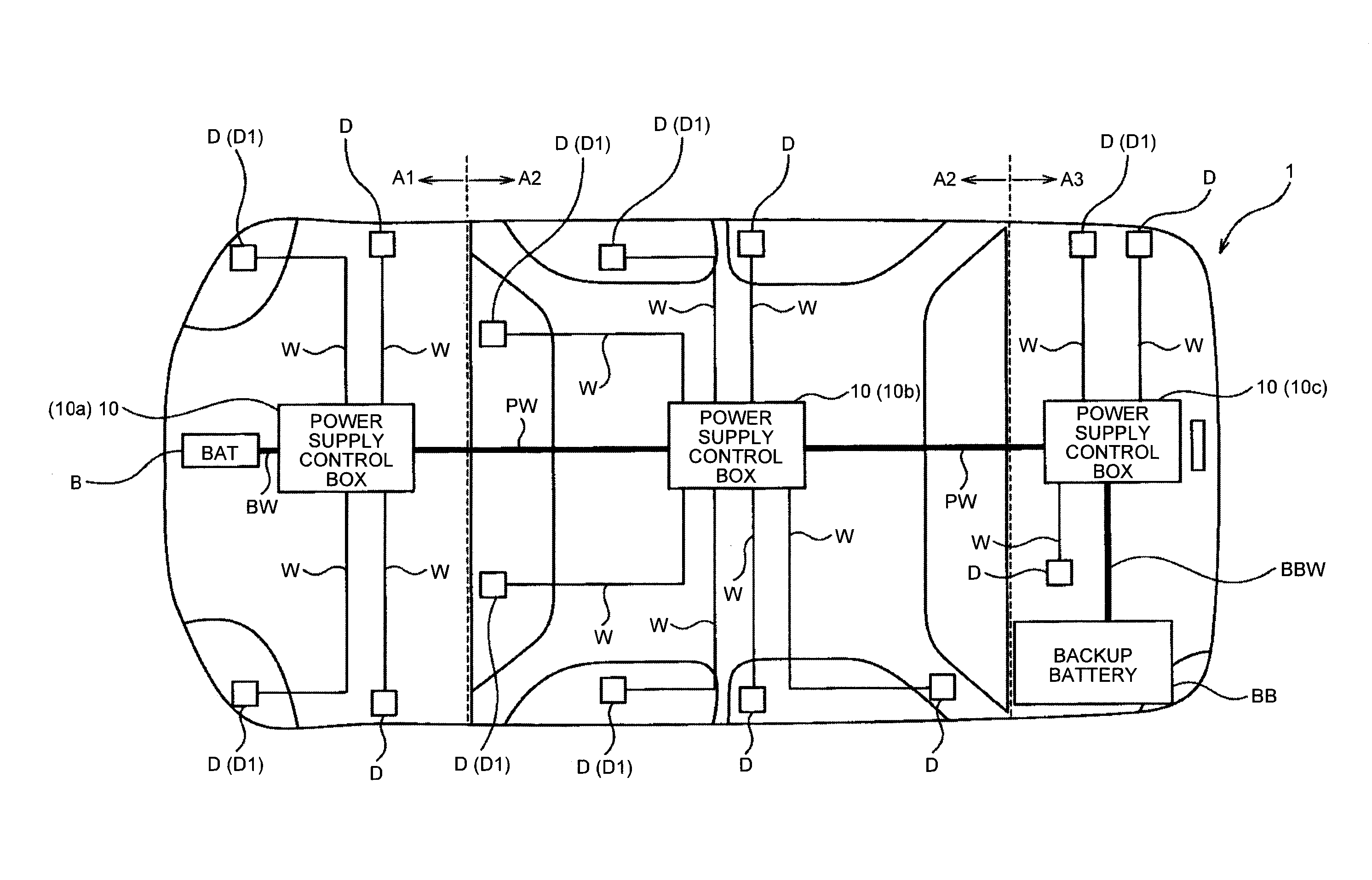
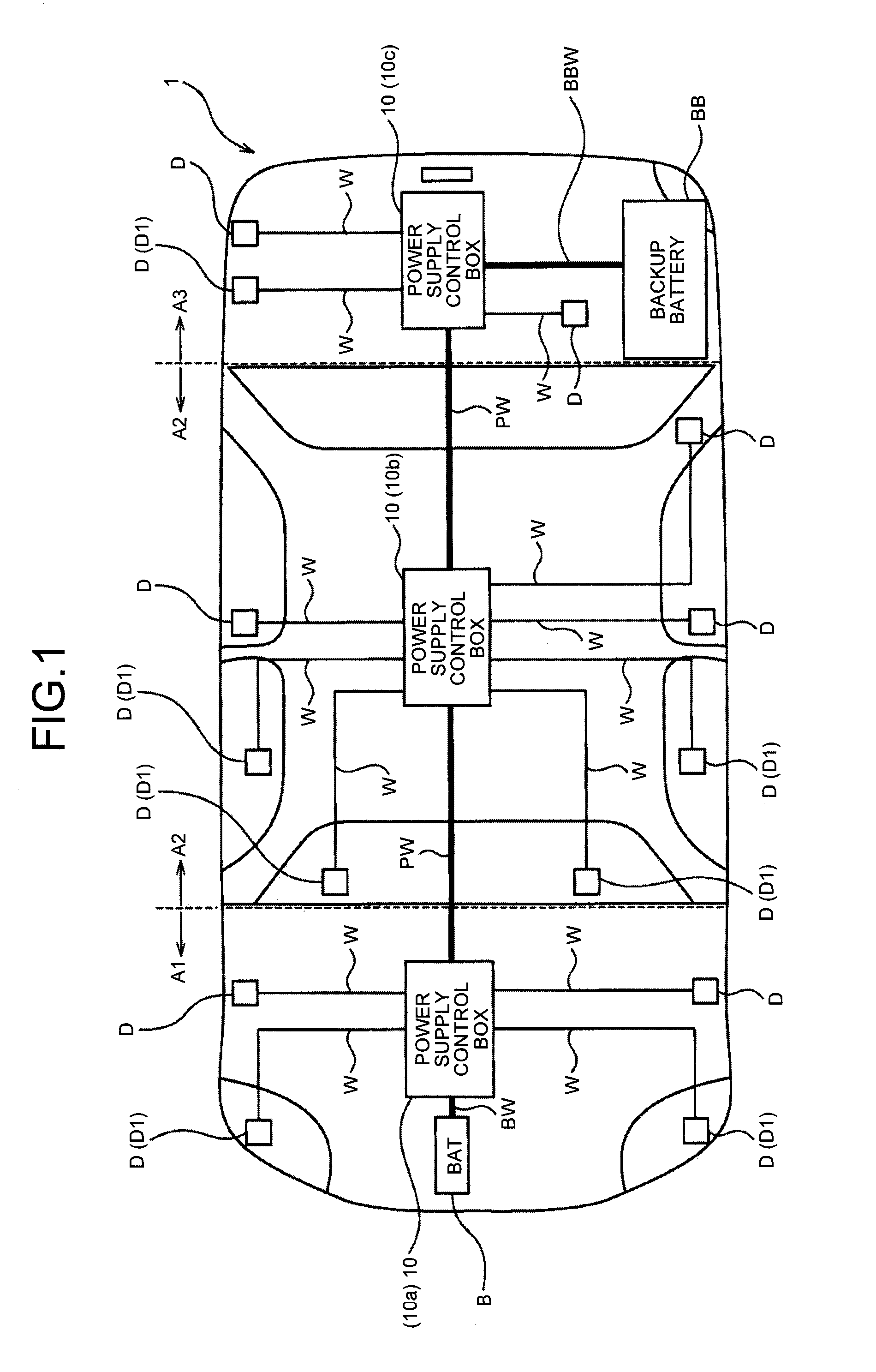
[0058]As described above, according to the backup battery system 1 the power supply wire PW connects the plurality of power supply control boxes 10 to each other, the vehicle battery B is connected to one (the first power supply control box 10a) of the power supply control boxes 10, and the backup battery BB is connected to a different one (the third power supply control box 10c). Accordingly, in a case where electric power supply from the vehicle battery B is retained, electric power from the vehicle battery B is supplied to the first power supply control box 10a, and is supplied from the first power supply control box 10a to the electric power required device D in the same section A1. In addition, electric power from the vehicle battery B reaches the power supply wire PW through the first power supply control box 10a, and is supplied to the second and third power supply control boxes 10b and 10c. In addition, electric power is supplied from each of the second and third power supp...

second embodiment

[0067]As described above, according to the backup battery system 2 it is possible to suppress an electric wire length while suppressing the number of backup batteries BB. In addition, even when electric power supply from the vehicle battery B is impossible, electric power from the backup battery BB can be transmitted to the power supply wire PW, which becomes an electric power supply route, through the switching.

[0068]In addition, the backup battery BB is disposed in the section A2 on the central side except for the sections A1 and A3 on the front end side and the rear end side of the vehicle. Accordingly, for example, even in a case where the vehicle battery B is mounted on a front side or a rear side of the vehicle, and the vehicle battery B may be broken due to collision on the front side of the vehicle or collision on the rear side of the vehicle, since the backup battery BB is provided in a section on the center side, the backup battery BB is less likely to be broken due to co...


PUM


Abstract

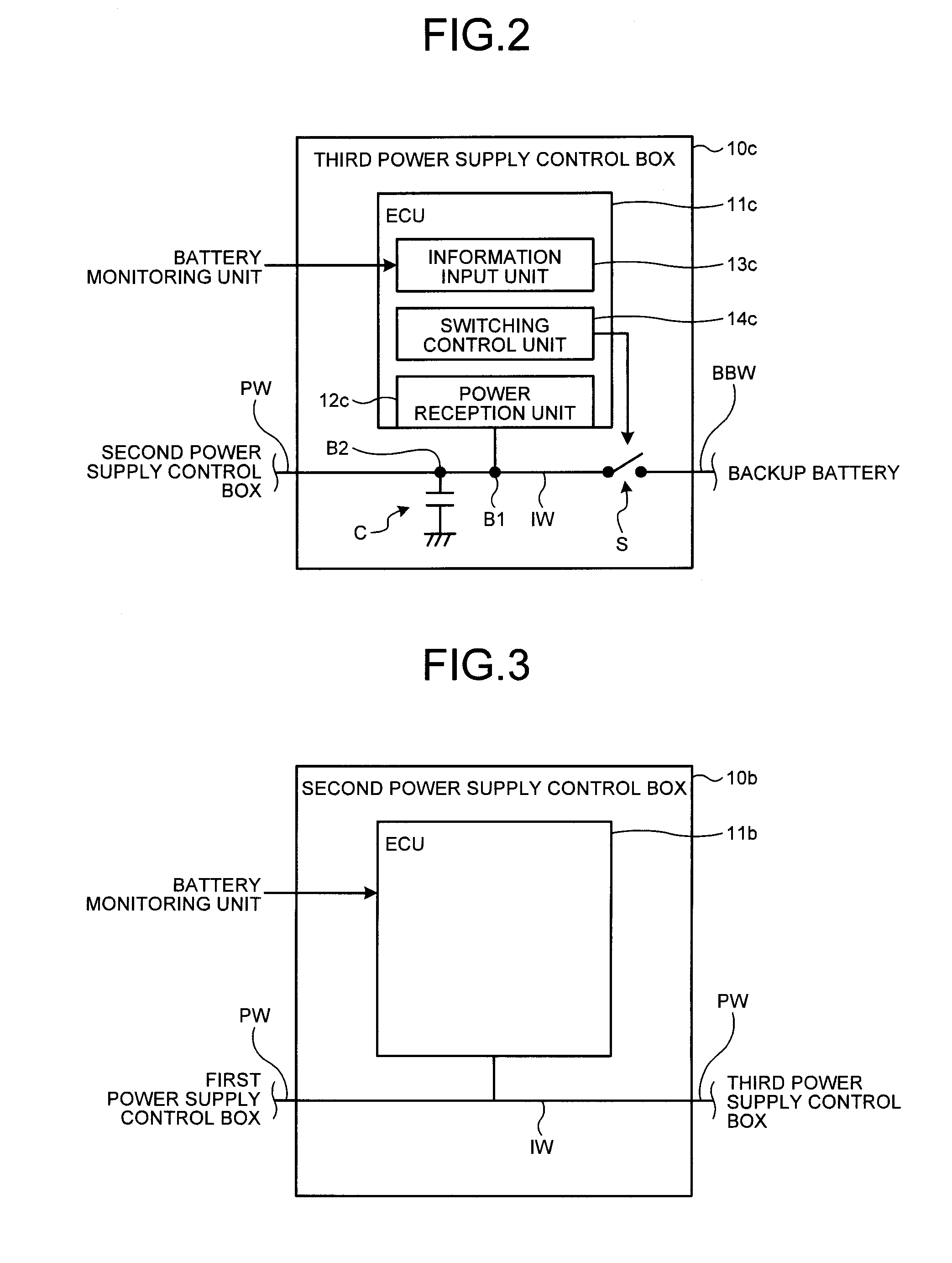
Provided is a backup battery system including a plurality of power supply control boxes which are disposed one by one in sections of a vehicle, each power supply control box distributes and supplies electric power received from a vehicle battery to electric power required devices, which include backup required devices and are provided in the section in which the power supply control box is disposed together; and a power supply wire that connects the plurality of power supply control boxes to each other. One of the plurality of power supply control boxes is connected to the vehicle battery, and another power supply control box is connected to a backup battery that becomes an electric power supply source when electric power supply from the vehicle battery is impossible.

Description

CROSS-REFERENCE TO RELATED APPLICATION(S)[0001]The present application claims priority to and incorporates by reference the entire contents of Japanese Patent Application No. 2015-141995 filed in Japan on Jul. 16, 2015.BACKGROUND OF THE INVENTION[0002]1. Field of the Invention[0003]The present invention relates to a backup battery system.[0004]2. Description of the Related Art[0005]In devices which receive power supply from a vehicle battery, a serious problem may occur when the power supply is shut off and thus the device does not operate. A backup battery, which is different from the vehicle battery, is connected to the devices for normal operation even when the power supply from the vehicle battery is shut off (for example, refer to Japanese Patent Application Laid-open No. 2014-180941).[0006]The inventors of the present application have made an examination with respect to a configuration in which a backup battery is connected to an important device similar to the invention descr...

Claims


Application Information

Patent Timeline
Patent Type & Authority Applications(United States)
IPC IPC(8): B60R16/033
CPCB60R16/033
Inventor KIKUCHI, HIDEAKI
Owner YAZAKI CORP
Learn More