
Methods, devices, and manufacture of the devices for musculoskeletal reconstructive surgery

a technology for reconstructive surgery and musculoskeletal muscle, which is applied in the field of methods, devices, and manufacture of musculoskeletal reconstructive surgery, and can solve the problems of bone resection, tissue die-back as well as pain at the harvest site, and surgeons must be very careful in their use of grafted bon

Active Publication Date: 2017-01-19
OHIO STATE INNOVATION FOUND +1
View PDF3 Cites 121 Cited by
  • Summary
  • Abstract
  • Description
  • Claims
  • Application Information

AI Technical Summary

Benefits of technology

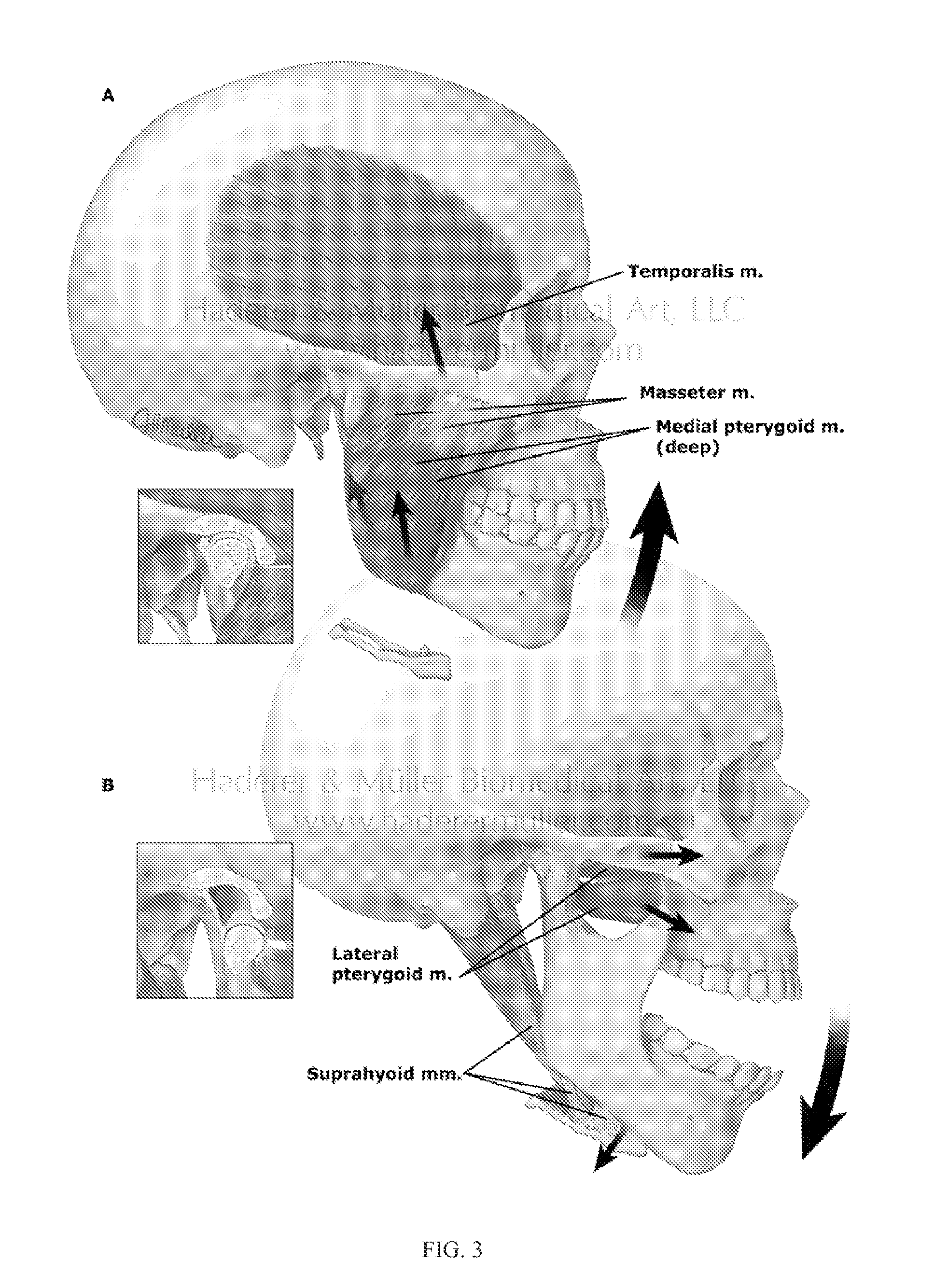
The present invention is a method and system that allows for the precise analysis and matching of the geometric and mechanical stress / strain trajectories needed in the reconstruction of an anatomically and functionally correct musculoskeletal element. This allows for the fabrication of patient-specific implants that closely match the patient's normal anatomy and function. The methods and systems can be applied to bone and various other organ systems in the body and can also be used to develop patient specific surgical guides. The invention also includes a method for determining a patient-specific stress / strain pattern based on 3D CT data and cross-sectional data of the major chewing muscles to design suitable implantation hardware to restore normal bite forces of the patient. Additionally, the invention provides a method for determining a patient-specific stress / strain pattern in order to tune the material used in fixation hardware to match the stiffness of the cortical bone as closely as possible while also providing sufficient strength to allow bone healing after reconstructive surgery.

Problems solved by technology

Cancer, trauma, osteopenia, joint degradation, or reconstructive surgery can result in resection of bone.
However, surgeons must be very careful in their use of grafted bone due to a limited supply from the patient's own body.
Not only is the supply very limited, but also, removal from a patient can result in tissue die-back as well as pain at the harvest site.
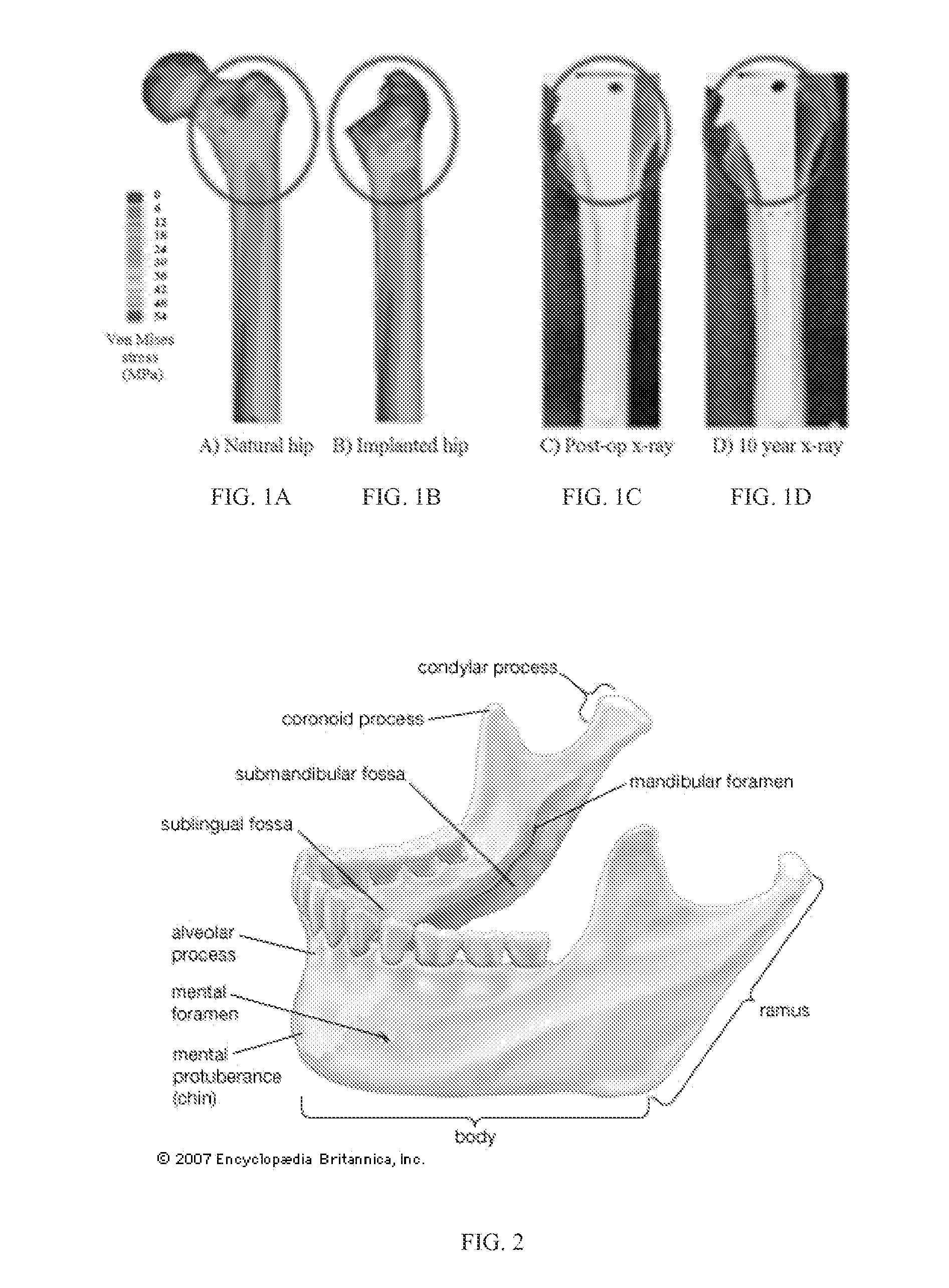
Once the reconstructed bones have healed, the localized stiffness of current fixation and joint replacement hardware results in stress shielding and stress concentrations that over time can break or loosen these devices or damage the surrounding bone.
As a result, these traditional implants can fail leading to pain.
If the stress-shielding reduces the load previously seen in areas fixated by or around the implant, those areas will not remodel and therefore will not regain their strength or may undergo subsequent resorption due to lack of loading.
Additionally, if stress is concentrated in areas that have not previously been exposed to high loads there can be damage to the bone that results in fracture.
Resorption resulting from post-implantation stress-shielding and / or the damage resulting from abnormal stress concentration can contribute to the breaking, failure, or loosening of the implant or the failure of grafted bone.
Traditional bone implants can have very different material properties from the surrounding anatomy (i.e., bone) to which they are attached, which can result in a mismatch of modulus between the implant and the surrounding anatomy.
This misoriented strain can result in pain in, and / or damage to, the surrounding anatomy.
Accordingly, even with optimized implant geometries, the traditional medical devices’ material stiffness mismatch with the surrounding anatomy can cause failure due to unhelpful stress shielding and / or stress concentrations.
This can cause loss of density over time in the surrounding anatomy that can lead to weakening of the surrounding anatomy and / or damage to the surrounding anatomy.
This change in stress regions can lead to pain, change, and / or damage to the surrounding anatomy.
The change and / or damage to the surrounding anatomy can occur over time.
Additionally, grafted bone may be at risk.
Although the grafted bone's form may resemble the bone previously occupying the space, the grafted bone may fail in areas of stress concentration or resorb in areas of stress shielding caused by adjacent, metallic segmental gap, joint replacement, and / or osteotomy fixation devices.
Because this hardware is often left in place after the bone has healed in place, it may subsequently cause stress shielding due to its high stiffness compared to the surrounding host bone.
This may result in resorption of the shielded bone (Rahmanian, R., et al., “Load bearing and stiffness tailored NiTi implants produced by additive manufacturing: a simulation study,” The International Society for Optical Engineering, San Diego, Calif.
This unfilled gap may also cause a loss of facial contour (Bähr, W., et al., “Use of the ‘double barrel’ free vascularized fibula in mandibular reconstruction,” Journal of Oral and Maxillofacial Surgery, 56(1): p.
This limitation is due to the maximum fibular length which is 24 cm.
The harvesting of a segment that is too long may increase the risk of donor site morbidity (He, Y., et al., “Double-barrel fibula vascularized free flap with dental rehabilitation for mandibular reconstruction,” Journal of Oral and Maxillofacial Surgery, 69(10): p.
This mismatch in stiffness between the traditional hardware and the graft / host bone can cause stress shielding at the implant-host tissue interface and stress concentration at fixation attachment sites.
The abnormal stress-strain distribution over time may lead to host-graft discontinuity and, under masticatory loading may risk implant failure.
By adding porosity to implants, larger surface areas within and around the implant are vulnerable to bacterial colonization.

Method used


Image

  • Methods, devices, and manufacture of the devices for musculoskeletal reconstructive surgery
  • Methods, devices, and manufacture of the devices for musculoskeletal reconstructive surgery
  • Methods, devices, and manufacture of the devices for musculoskeletal reconstructive surgery

Examples


example

Patient Specific Implant Design: Geometry and Material Properties For Reconstruction of the Mandible

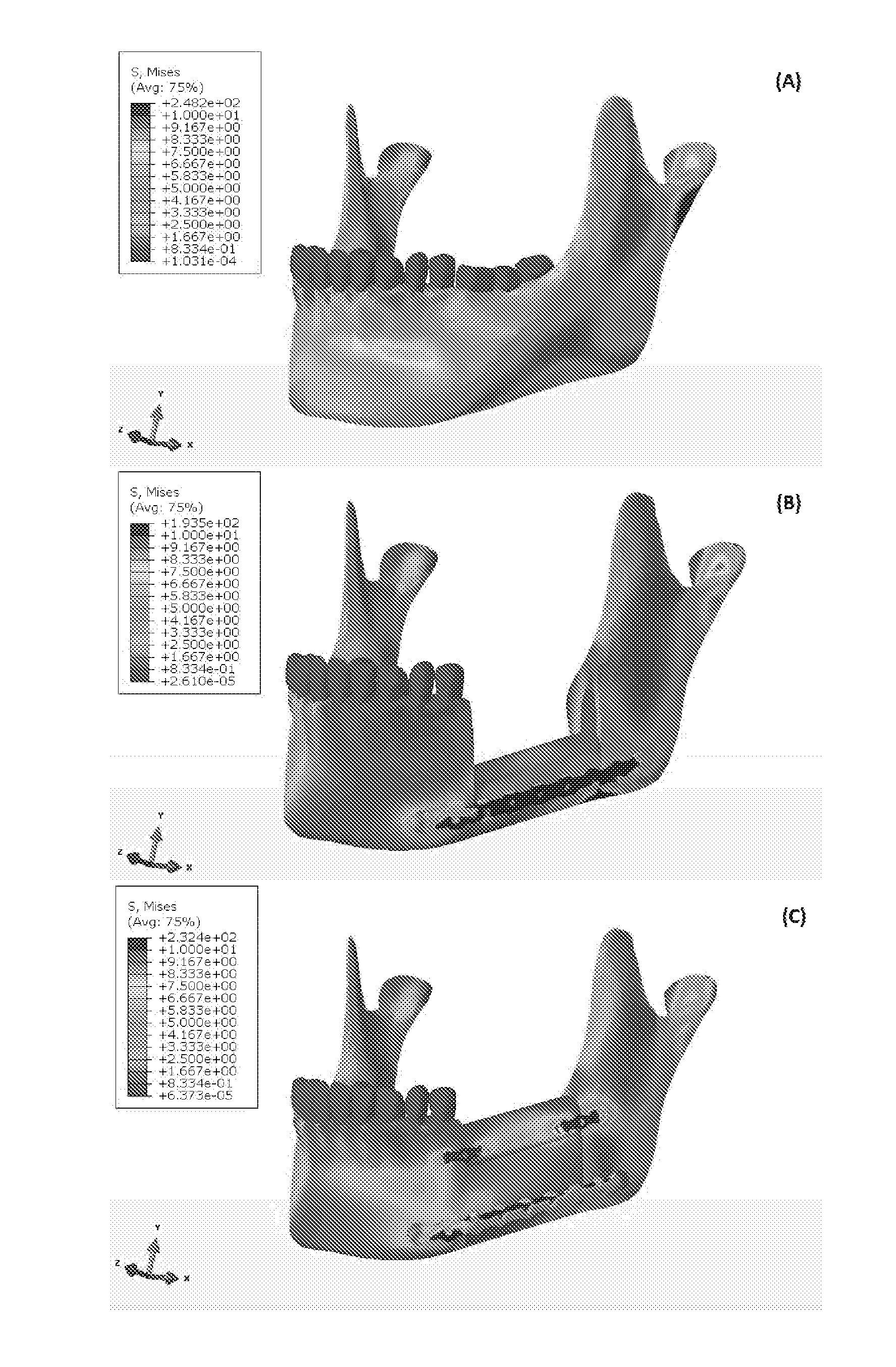
[0130]Tumor resection, trauma, and inflammation cause mandibular segmental defects (i.e., a complete segment is missing resulting in two separate parts), which may lead to airway obstruction, disfigurement, disturbance in speech and swallowing, and diminished masticatory ability. Reconstruction methods and techniques need to be applied to restore the mandible aesthetic and function, including repair of mandible continuity and muscles attachment. Despite all the progress in surgically treating this condition over the last 30-40 years, none of the current techniques meet all the needs to completely restore the shape and functionality of the lost bone over the long term (e.g., more than 10 years) (Abbas A., “Reconstruction skeleton for the lower human jaw using CAD / CAM / CAE,” Journal of King Saud University-Engineering Sciences, 24:159-64 (2012)). At present, the standard of care for a se...


PUM


Abstract

A device used in conjunction with fixation hardware to provide a two-stage process to address the competing needs of immobilization and re-establishment of normal stress-strain trajectories in grafted bone. A method of determining a patient-specific stress / strain pattern that utilizes a model based on 3D CT data of the relevant structures and cross-sectional data of the three major chewing muscles. The forces on each of the chewing muscles are determined based on the model using predetermined bite forces such that a stiffness of cortical bone in the patient's mandible is determined. Based on the stiffness data, suitable implantation hardware can be designed for the patient by adjusting external topological and internal porous geometries that reduce the stiffness of biocompatible metals to thereby restore normal bite forces of the patient.

Description

CROSS-REFERENCE TO RELATED APPLICATIONS[0001]This application is a non-provisional of and claims priority to U.S. Provisional Application No. 61 / 951,028, filed on Mar. 11, 2014 and U.S. Provisional Application No. 62 / 110,281, filed on Jan. 30, 2015. The contents of both provisional applications are incorporated by reference herein.BACKGROUND OF THE INVENTION[0002]Cancer, trauma, osteopenia, joint degradation, or reconstructive surgery can result in resection of bone. As a result, there is a significant and growing need for developing new sources of transplanted bone and bone substitute materials as well as developing surgical plans for how those materials will interact with artificial joints and fixation strategies that are aimed at restoring or creating normal musculoskeletal function. Currently, the standard of care for an area of bone deficit is to graft the patient's own bone to a defect site. However, surgeons must be very careful in their use of grafted bone due to a limited s...

Claims


Application Information

Patent Timeline
IPC IPC(8): A61B17/80A61F2/28A61F2/30A61B34/10
CPCA61B17/8071A61B34/10A61F2/2803A61F2/30942A61F2002/3092A61B2034/104A61B2034/105A61B2034/108A61F2002/30303A61B2017/00004A61F2002/30014A61F2002/30962
Inventor DEAN, HOWARD DAVIDELAHINIA, MOHAMMAD H.HABERLAND, CHRISTOPHMILLER, MICHAEL J.SUTRADHAR, ALOKMOGHADDAM, NARGES SHAYESTEHWALKER, JASON M.SKORACKI, ROMAN
Owner OHIO STATE INNOVATION FOUND
Learn More