Eureka AIR delivers breakthrough ideas for toughest innovation challenges, trusted by R&D personnel around the world.

Apparatus and Method for Providing an Alternate Flow Path in Isolation Devices

a technology of isolation device and flow path, which is applied in the direction of wellbore/well accessories, fluid removal, earthwork drilling and mining, etc., can solve the problems of not fully addressing the complexities of providing fluid barrier and/or fluid isolation using swellable elastomer systems, and the use of conventional wellbore packers, etc., to achieve the effect of improving operation and reducing the effect of operation

Active Publication Date: 2010-06-24
WEATHERFORD UK LIMITED
View PDF8 Cites 108 Cited by
  • Summary
  • Abstract
  • Description
  • Claims
  • Application Information

AI Technical Summary

Benefits of technology

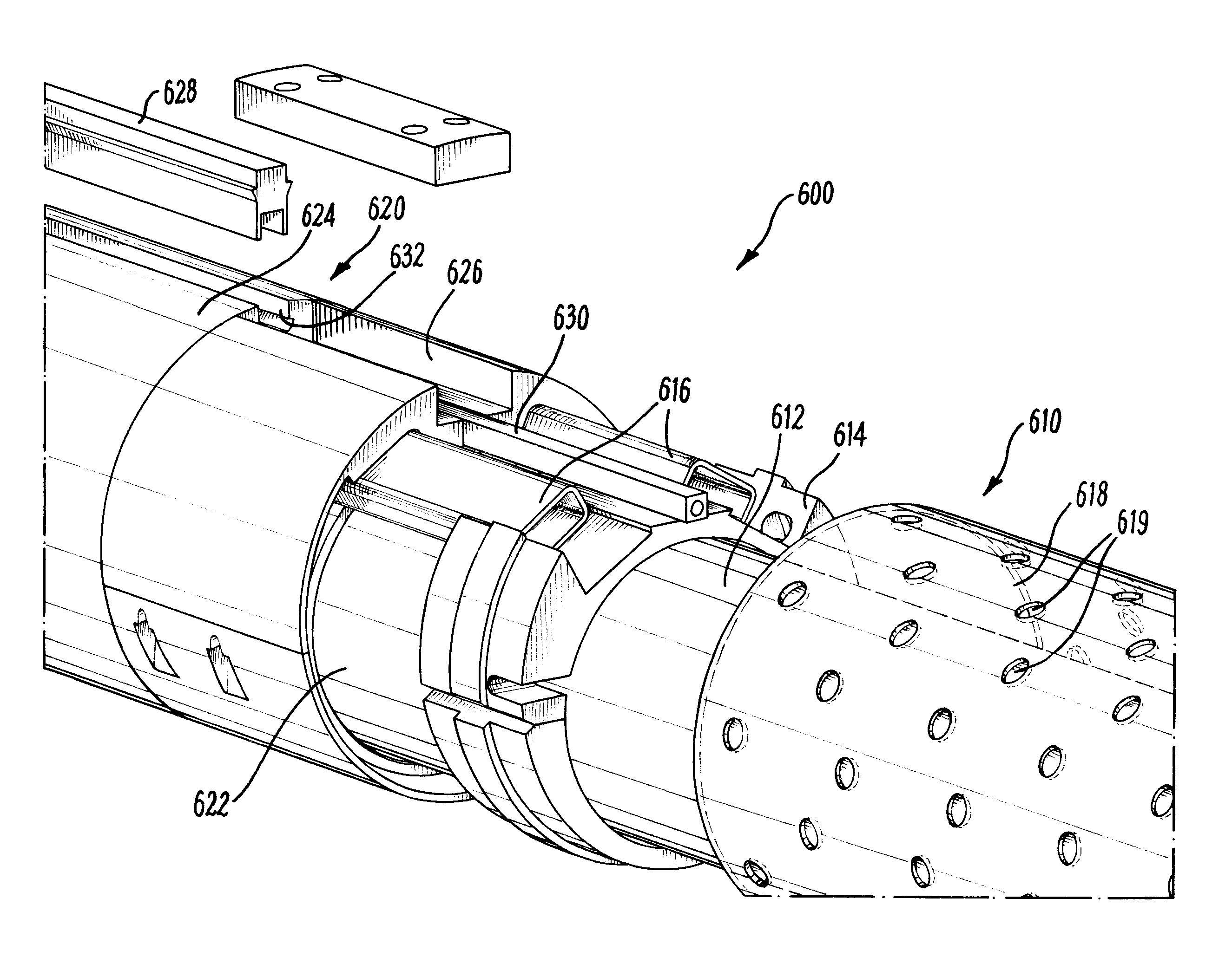
[0017]By varying the secondary flow path, the apparatus of the invention is configured for improved operation of the expanding element of the apparatus. For example, the required annular barrier and / or sealing function of the expanding element can be maintained even with the provision of the secondary flow path through the apparatus. The conduit is configured to have a reduced effect on the operation of the expanding element, while still allowing the conduit to be coupled to alternate flow paths of adjacent apparatus.
[0018]The apparatus may be a wellbore packer, configured to provide a seal in the space between the tubular body and the surrounding wall. The apparatus may alternatively be configured to provide an annular barrier which inhibits fluid flow in the space and / or prevents the movement of solid particles in the annulus.
[0021]The conduit may be arranged to vary a radial dimension of the secondary flow path. The conduit may be arranged to vary the secondary flow path by changing the direction of fluid flowing in the secondary flow path. In particular, the conduit may be arranged to change the radial distance of the flow path from the longitudinal axis of the apparatus. Thus the radial position of the flow path can be selected to improve the operation of the expanding element. Embodiments of the invention therefore have the advantage that the apparatus can be used with standard alternate flow path and shunt tube configurations adopted by various manufacturers of alternate paths and control systems.
[0025]Alternatively, or in addition, the conduit may be arranged to vary the secondary flow path by changing the cross-sectional profile of the conduit along the longitudinal direction of the apparatus. This may for example allow the conduit or a portion of it to be repositioned within the apparatus in order to have a minimal impact on the operation of the expanding element. It may also allow the flow area to be redistributed about the circumference of the apparatus to reduce the radial dimension of the flow path.

Problems solved by technology

Use of alternate path screen systems creates difficulties in wellbore isolation.
In particular, alternate paths prevent the use of conventional wellbore packers to isolate multiple production zones.
However, WO 2007 / 092082 and WO 2007 / 092083 do not fully address the complexities of providing fluid barriers and / or fluid isolation using swellable elastomer systems.
For example, WO 2007 / 092082 and WO 2007 / 092083 are concerned with providing a continuous flow path, but do not address the problems of maintaining the required annular barrier or fluid seal functions of the packer with the provision of the secondary flow path through the apparatus.
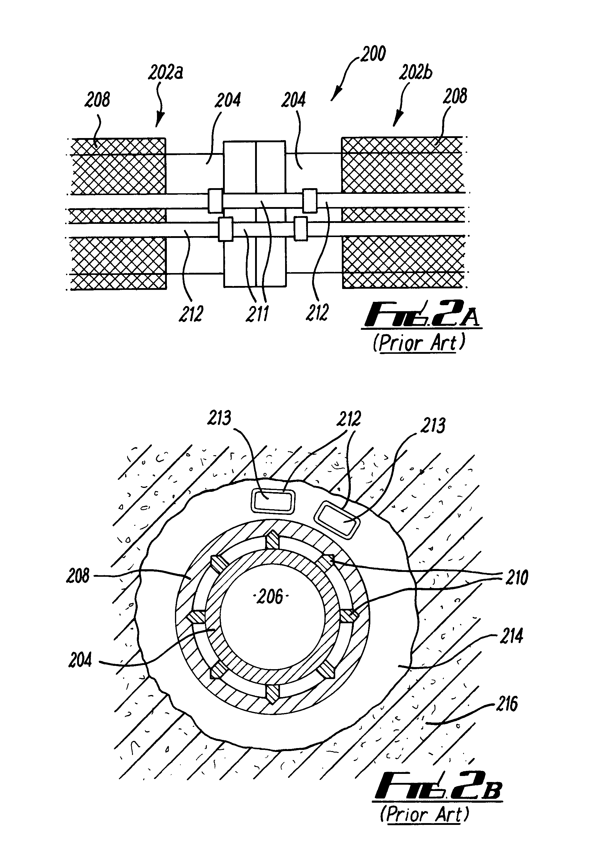
Such problems may arise due to removal of a volume of elastomer from the isolation device, improper sealing around the conduits, displacement of the conduits due to expansion of the element, and / or coupling of the conduits at opposing ends of the isolation device.
This configuration would limit the swelling performance from a swellable mantle as it provides minimal mantle thickness.
In addition, configuring a swellable elastomer well packer to achieve a seal at a fully swollen condition may mean extremely long or impractical sealing times and marginal pressure sealing performance if the swellable mantle did manage to contact the wellbore.
The arrangement which comprises a manifold would also be inefficient in finding a nominal balance of swellable mantle thickness.
This may compromise the integrity of the seal provided by the expanding element and / or increase the time to seal.
This limits swelling performance and can impact on the success of deployment operations.

Method used


Image

  • Apparatus and Method for Providing an Alternate Flow Path in Isolation Devices
  • Apparatus and Method for Providing an Alternate Flow Path in Isolation Devices
  • Apparatus and Method for Providing an Alternate Flow Path in Isolation Devices

Examples


Embodiment Construction

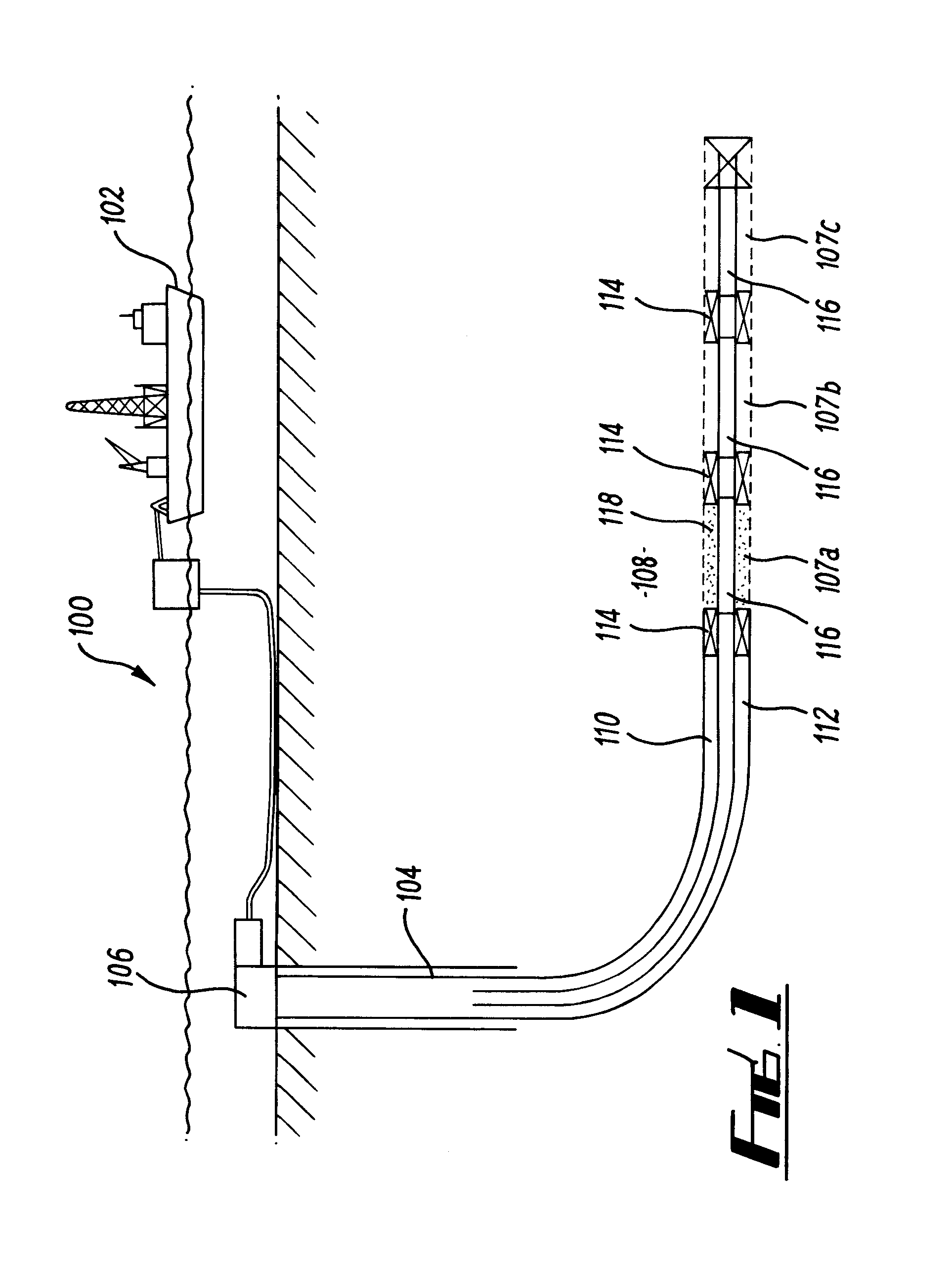
[0056]Referring firstly to FIGS. 3A to 3C, there is shown an apparatus in accordance with an embodiment of the invention. The apparatus is a wellbore packer configured to provide an annular seal in an annulus between a production tubing and the wellbore wall of an openhole system. The packer is configured in particular for use in a multi-zone production system, such as that shown in FIG. 1, and is configured for attachment with alternate sand control devices which comprise shunt tubes for delivery of gravel packs to production intervals. FIG. 3A is a longitudinal section through the apparatus 300, and FIGS. 3B and 3C are respectively cross-sectional views through lines B-B′ and C-C′.

[0057]The packer 300 comprises a tubular body 302 which has a longitudinal axis A and a throughbore 304. The tubular body 302 is provided with couplings (not shown at each end), configured for connection in the production string. In this embodiment, the couplings are suitable for connecting the packer to...


PUM


Abstract

An apparatus for use in a wellbore is described, the apparatus having a tubular body and a throughbore which defines a primary fluid path through the apparatus. An expanding element is disposed around the tubular body and is configured to provide an annular barrier in a space between the tubular body and a surrounding wall. A conduit defining a secondary flow path through the apparatus is provided, and is configured to be in fluid communication with at least one alternate path, such as a shunt tube. The conduit is arranged to vary the secondary flow path along a longitudinal direction of the apparatus, for example to redirect the flow path to a radial position closer to the tool body. The conduit is configured to have a reduced effect on the operation of the expanding element, while still allowing the conduit to be coupled to alternate flow paths of adjacent apparatus.

Description

CROSS-REFERENCE TO RELATED APPLICATIONS[0001]This application claims priority United Kingdom Patent Application No. GB0820619.5, filed on Nov. 11, 2008, which is hereby incorporated by reference in its entirety.FIELD OF THE INVENTION[0002]The present invention relates to an apparatus and method for use in wellbores for the hydrocarbon exploration and production industry. The invention relates particularly, although not exclusively, to an apparatus and method for providing an alternate flow path in isolation devices.BACKGROUND[0003]In the field of oil and gas exploration and production, various tools are used to provide barriers in the wellbore which prevent or restrict the fluid flow. A wellbore packer provides a seal in the annular space between two tubing strings, or between an outer casing and an open hole. A packer may be run with a completion string to a downhole location, and may be inflated or expanded into contact with the outer casing or open hole. The packer may be designe...

Claims


Application Information

Patent Timeline
Patent Type & Authority Applications(United States)
IPC IPC(8): E21B43/04E21B33/047
CPCE21B43/04E21B33/1208E21B33/124E21B33/12
Inventor NUTLEY, KIMNUTLEY, BRIAN
Owner WEATHERFORD UK LIMITED
Why Eureka
Eureka Blog
Learn More