
Receiver, communication unit, and method for down-converting a radio frequency signal

a radio frequency signal and receiver technology, applied in adaptive networks, complex mathematical operations, impedence networks, etc., can solve the problems of inability to provide a well-defined, real input termination at frequencies around sampling frequencies, and dtfs, while naturally performing down-conversion (aliasing), so as to achieve less space, less cost, and high capacitance density

Active Publication Date: 2017-01-12
MEDIATEK SINGAPORE PTE LTD SINGAPORE
View PDF3 Cites 1 Cited by
  • Summary
  • Abstract
  • Description
  • Claims
  • Application Information

AI Technical Summary

Benefits of technology

The patent suggests using MOS capacitors for certain parts of a semiconductor device. This results in higher capacitance density, which means the device can be made more compact and cost-effective. Compared to other types of capacitors, MOS capacitors require less area and have lower costs.

Problems solved by technology

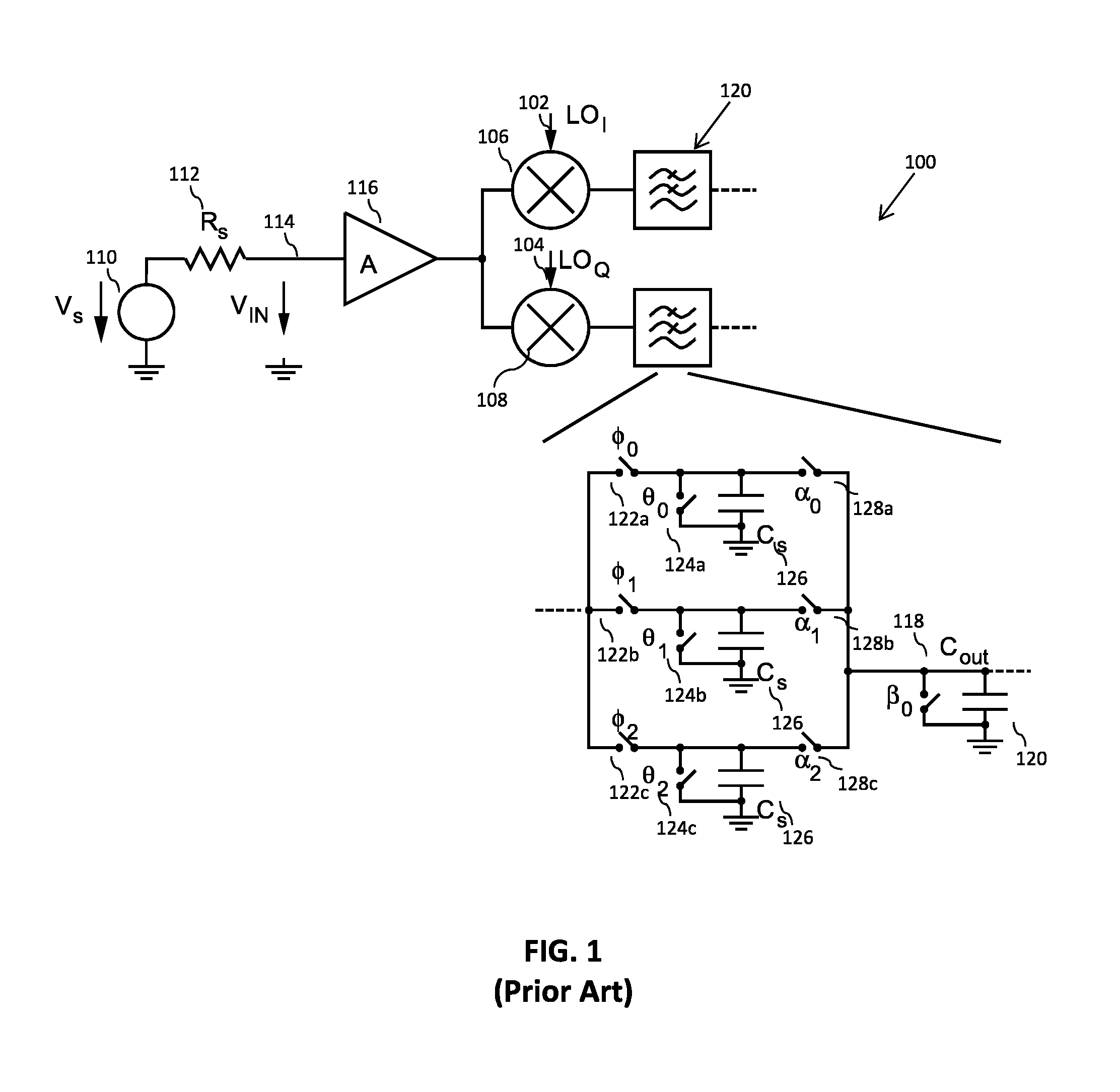
The N-branch parallel discrete time filter 120 in FIG. 1, in a form of a Finite Impulse Response (FIR) filter, is not suitable as a radio frequency (RF) input stage for a receiver due to it's reactive input termination and large input noise bandwidth.
Thus, DTFs, whilst able to naturally perform down-conversion (aliasing), fail to provide a well-defined, real, input termination at frequencies around the sampling frequency.
In addition, they generally add a substantial amount of noise by folding noise around harmonics of the sampling frequency on top of the wanted signal (aliasing).
This is because of the non-linear characteristic of the devices used to implement them (generally, transistors) and because the high operating frequency limits the use of analogue linearization techniques such as feedback.
In addition the power consumption of the input analogue circuits is usually a sizable fraction of the total power consumption of the receiver.

Method used


Image

  • Receiver, communication unit, and method for down-converting a radio frequency signal
  • Receiver, communication unit, and method for down-converting a radio frequency signal
  • Receiver, communication unit, and method for down-converting a radio frequency signal

Examples


Embodiment Construction

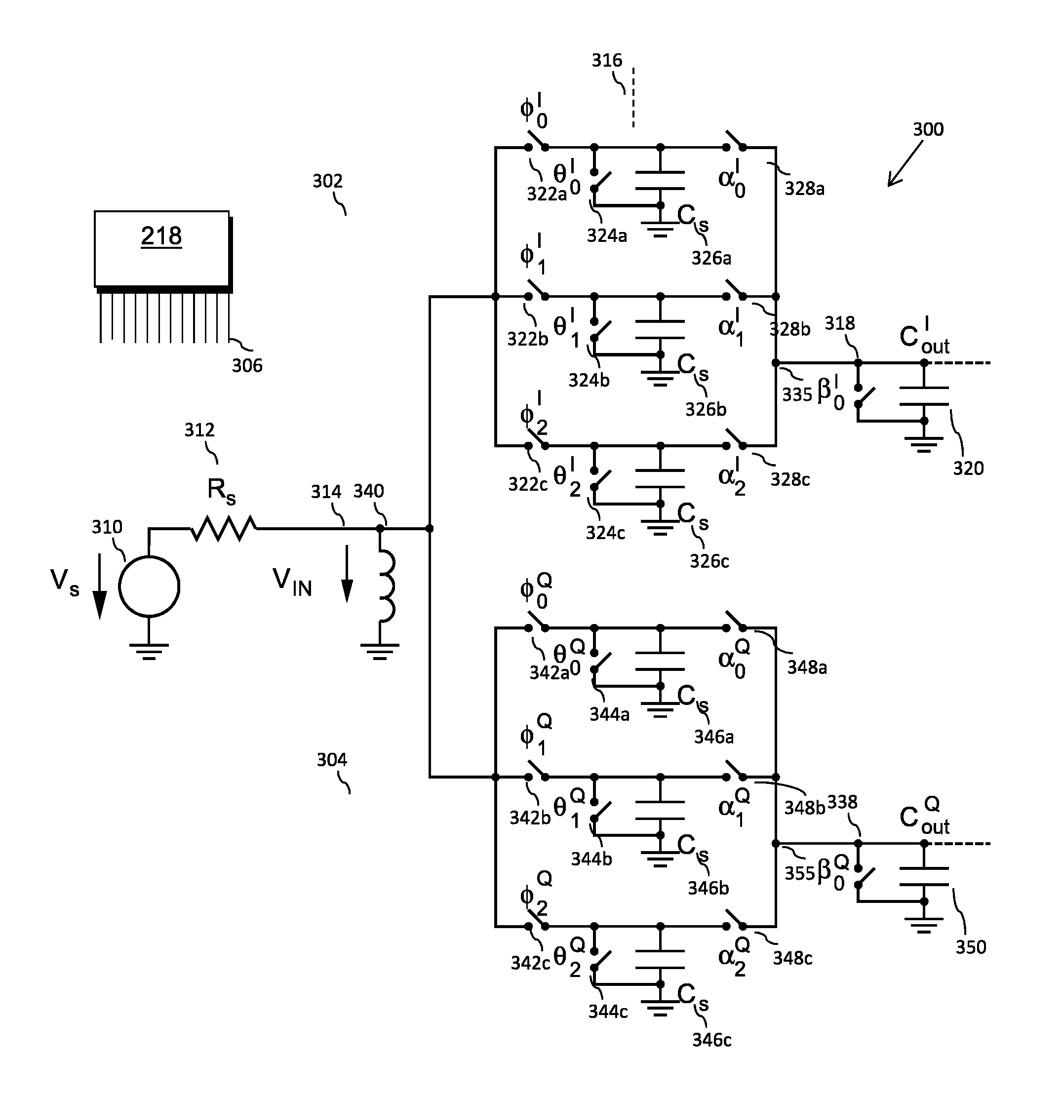
[0030]Examples of the invention will be described in terms of a hardware-based discrete-time filter design. However, it will be appreciated by a skilled artisan that the inventive concept herein described may be embodied in any type of discrete-time filter design, e.g. software, firmware or any combination thereof. Although examples of the invention are described with reference to a DTF for a wireless communication unit, it is envisaged that the disclosed DTF may be applied to a multitude of everyday electronic components and products, such as mobile radios, radio receivers, audio-video receivers, etc.

[0031]In accordance with some example embodiments of the invention, the inventor has recognized and appreciated that switching transients are a major contributor in creating the real part of the input impedance for a radio frequency filter, particularly a finite impulse response (FIR) discrete time filter that could be designed to function as a radio frequency filter.

[0032]A communicat...


PUM


Abstract

There is provided a communication receiver comprising: an input for receiving a radio frequency, RF, input signal; and at least one finite impulse response, FIR, discrete time filter, DTF. The at least one FIR DTF comprises: an input circuit comprising an input port for sampling the RF input signal at a sampling frequency that is comparable to the input RF input signal; and N parallel branches, each branch having a set of input unit sampling capacitances, where each unit sampling capacitance is independently selectively coupleable to an output summing node. The input circuit is configured to convert an equivalent input impedance of the at least one FIR DTF around the sampling frequency to a real impedance.

Description

FIELD OF THE INVENTION[0001]The field of this invention relates to a receiver and a communication unit comprising a receiver having a discrete time filter and method for receiving and down-converting a radio frequency signal therein.BACKGROUND OF THE INVENTION[0002]A primary function of a wireless receiver is to down-convert the received wanted radio frequency signal to a baseband and / or digital form in order to process the wanted signal. In order to selectively extract the wanted signal from noise or other undesired signals, filters are used. Filters are employed at various stages of a receiver's architecture, from analog radio frequency (RF) filters through to digital filters. A digital filter operates on a discrete time sample set, where the value of the samples has been rounded to the nearest value from a finite set of possible values, typically represented as a binary number.[0003]An analog discrete time filter (DTF) operates on a discrete time sample set, where the value of th...

Claims


Application Information

Patent Timeline
Patent Type & Authority Applications(United States)
IPC IPC(8): H04B1/26H04B1/00
CPCH04B1/26H04B1/0017H04B1/0014H03H15/00G06F17/11H03H15/023H03H21/0023
Inventor BEFFA, FEDERICO ALESSANDRO FABRIZIO
Owner MEDIATEK SINGAPORE PTE LTD SINGAPORE
Learn More