
Signal transmission apparatus and multicarrier communication system

a transmission apparatus and multi-carrier technology, applied in the field of communication, can solve the problems of affecting the stability of the transmission system, affecting the accuracy of the transmission performance, and the nonlinearity of the actual system, so as to improve the accuracy of the nonlinear channel signal to noise ratio probing, accurately predicting transmission performance, and reducing deviation

Active Publication Date: 2016-12-29
FUJITSU LTD
View PDF1 Cites 2 Cited by
  • Summary
  • Abstract
  • Description
  • Claims
  • Application Information

AI Technical Summary

Benefits of technology

The present disclosure is aimed at improving the accuracy and reliability of signal transmission in a communication system. It introduces a signal transmission apparatus and multicarrier communication system that can predict transmission performance accurately based on a correct signal to noise ratio and recommended signal configuration. This allows for flexible system adaptive control reception, ensuring reliability and stability of the communication system. The system probes channel SNR based on multiple times of recursion to reduce deviation of signal to noise ratio and improve accuracy of nonlinear channel signal to noise ratio probing.

Problems solved by technology

Being limited to hardware process and cost, nonlinearity usually exists in an actual system.
The nonlinearity will make a signal to noise ratio measured in a probing stage unable to accurately feature a signal to noise ratio at an actual transmission stage, and transmission configuration obtained based on the inaccurate signal to noise ratio at the probing stage is also not optimal, influence of which being directly embodied by great increase of a probability of out-of-range of a bit error at the actual transmission stage, thereby greatly affecting stability of the transmission system.
A method counteracting such deviation in an existing system and application is at a cost of sacrificing efficiency of the system, artificially preserving sufficient performance margins.
However, for a future communication application of a high rate, a high density and a low cost, the method of artificially preserving sufficient performance margins will obviously applicable no longer.

Method used


Image

  • Signal transmission apparatus and multicarrier  communication system
  • Signal transmission apparatus and multicarrier  communication system
  • Signal transmission apparatus and multicarrier  communication system

Examples


embodiment 1

[0057]An embodiment of the present disclosure provides a signal transmission apparatus. FIG. 3 is a schematic diagram of a structure of the signal transmission apparatus of the embodiment of the present disclosure. As shown in FIG. 3, the signal transmission apparatus 300 includes:[0058]a first receiving unit 301 configured to receive a probe signal transmitted by a transmitting end; the probe signal is generated according to characteristics of recommended signal configuration obtained by previous one or more times of signal to noise ratio probing;[0059]a first processing unit 302 configured to probe a channel signal to noise ratio according to the probe signal;[0060]a first determining unit 303 configured to determine transmission signal configuration and signal transmission performance according to a final channel signal to noise ratio obtained by multiple times of signal to noise ratio probing; and[0061]a first transmitting unit 304 configured to transmit the transmission signal ...

embodiment 2

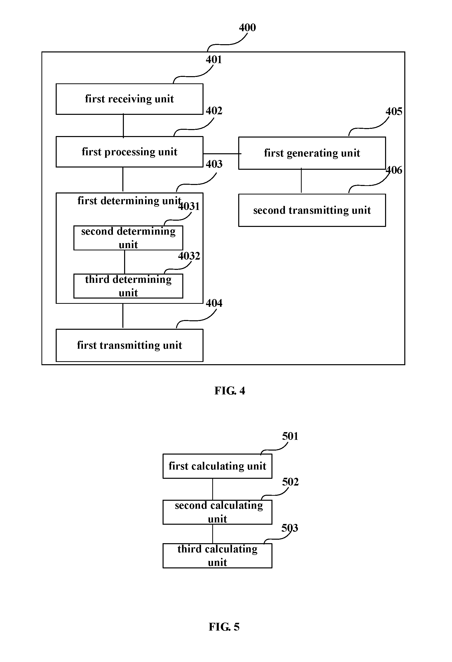
[0068]An embodiment of the present disclosure provides a signal transmission apparatus. FIG. 4 is a schematic diagram of a structure of the signal transmission apparatus of the embodiment of the present disclosure. As shown in FIG. 4, the signal transmission apparatus 400 includes a first receiving unit 401, a first processing unit 402, a first determining unit 403 and a first transmitting unit 404, implementations of which being identical to those of the first receiving unit 301, the first processing unit 302, the first determining unit 303 and the first transmitting unit 304 in Embodiment 1, and being not going to be described herein any further.

[0069]In this embodiment, as shown in FIG. 4, in order that the transmitting end generates probe signals containing whole or partial characteristics of more actually transmitted signals, and reduces deviation between a signal to noise ratio probed at the latter time of recursion and a signal to noise ratio at the actual transmission stage,...

embodiment 3

[0095]An embodiment of the present disclosure provides a signal transmission method, corresponding to the signal transmission apparatus in Embodiment 1 or 2, with identical contents being not going to be described herein any further.

[0096]FIG. 16 is a flowchart of the signal transmission method of the embodiment of the present disclosure. As shown in FIG. 16, the signal transmission method includes:[0097]step 1601: receiving a probe signal transmitted by a transmitting end; the probe signal is generated according to characteristics of recommended signal configuration obtained by previous one or more signal to noise ratio probing;[0098]step 1602: probing a channel signal to noise ratio according to the probe signal;[0099]step 1603: determining transmission signal configuration and signal transmission performance according to a final channel signal to noise ratio obtained by multiple times of signal to noise ratio probing; and[0100]step 1604: transmitting the transmission signal confi...


PUM


Abstract

A signal transmission apparatus and multicarrier communication system that includes: a first receiving unit configured to receive a probe signal transmitted by transmitting end; wherein, the signal is generated according to characteristics of recommended signal configuration obtained by previous signal to noise ratio (SNR) probings; a first processing unit configured to probe a channel SNR according to the signal; a first determining unit configured to determine transmission signal configuration and signal transmission performance according to a final channel SNR obtained by multiple times of SNR probing; and a first transmitting unit configured to transmit the configuration and the performance to the transmitting end, so that the transmitting end transmits an actual transmission signal according to the configuration and the performance. With the embodiments, accuracy of probing a nonlinear channel SNR is improved, and reliability and stability of the communication system are guaranteed.

Description

CROSS-REFERENCE TO RELATED APPLICATIONS[0001]This application is a continuation application, filed under 35 U.S.C. §111(a), of International Application PCT / CN2015 / 073599 filed on Mar. 4, 2015 and claims foreign priority to Chinese Patent Application No. 201410083273.7, filed Mar. 7, 2014, the content of which is incorporated herein by reference in its entirety.BACKGROUND[0002]1. Field[0003]The present disclosure relates to the field of communications, and in particular to a signal transmission apparatus and multicarrier communication system.[0004]2. Description of the Related Art[0005]A multicarrier communication system is a communication system based on multicarrier modulation, which is widely used in wireless and access networks at present due to its advantages, such as high transmission rate, high spectral efficiency, and multipath and frequency domain fading proof, and to which wide attention is paid and studied as being taken as an important solution for future higher speed an...

Claims


Application Information

Patent Timeline
IPC IPC(8): H04L27/26H04L25/02H04L1/20
CPCH04L27/2601H04L27/2646H04L25/0202H04L1/20H04J11/00H04B10/0775H04L1/0003H04L1/203H04L5/0046H04L5/006H04W52/08H04L1/0025H04L5/0048
Inventor CHEN, HAOLI, LEIYAN, WEIZHENLIU, BO
Owner FUJITSU LTD
Learn More