
Multi-head array fire sprinkler system

a sprinkler system and multi-head technology, applied in the field of sprinklers, can solve the problems of inability to place side-discharge sprinklers near each other, inability to use side-discharge sprinklers in open surround conditions, and inability to reduce the risk of “cold soldering” and other problems, to achieve the effect of saving both material and labor, eliminating certain weaknesses inherent in each orientation, and improving fire protection

Active Publication Date: 2016-12-29
FIREBIRD SPRINKLER COMPANY
View PDF4 Cites 6 Cited by
  • Summary
  • Abstract
  • Description
  • Claims
  • Application Information

AI Technical Summary

Benefits of technology

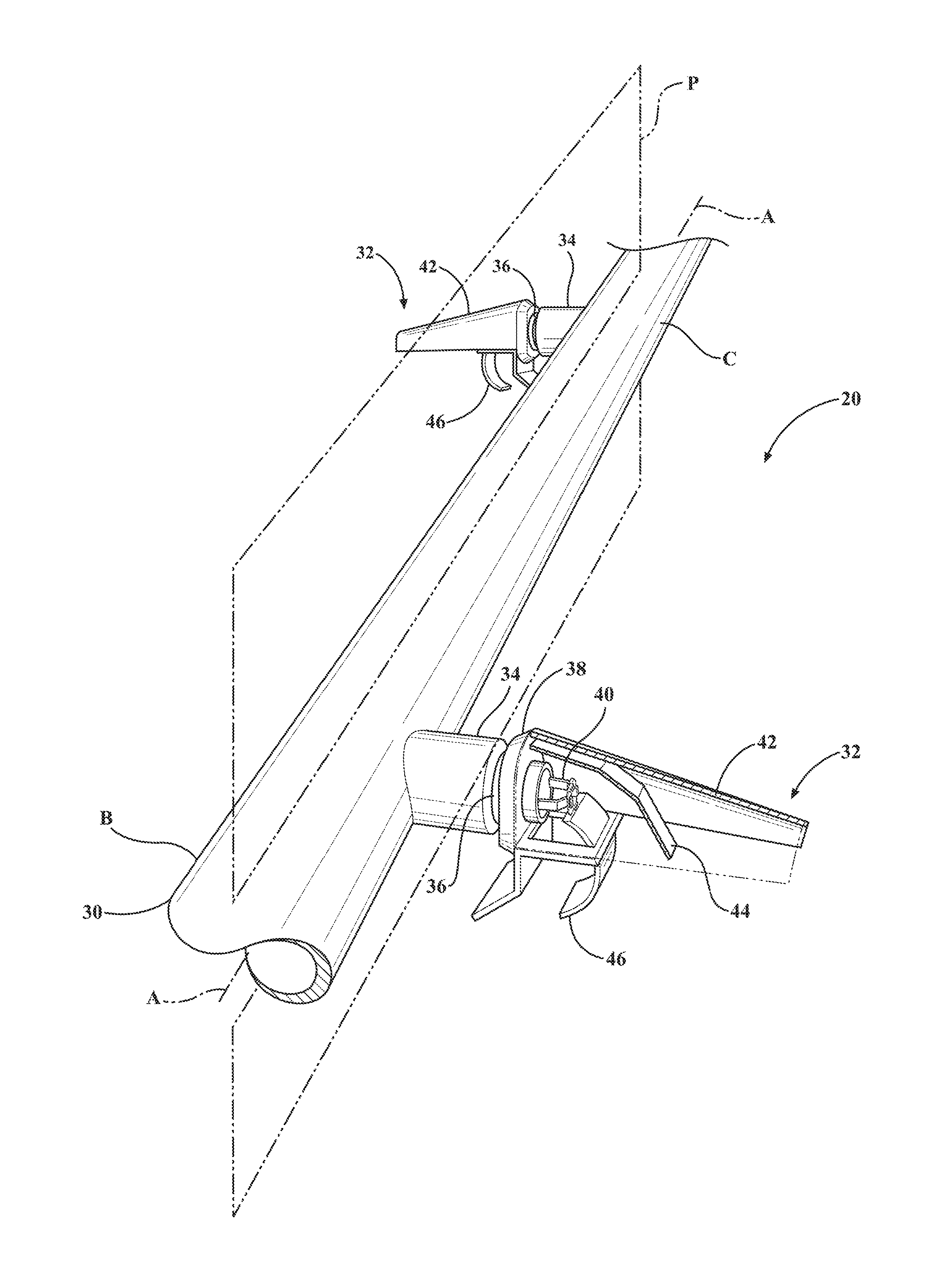
[0014]This present invention enables the advantageous combination of multiple orientations of fire sprinklers, thus combining the respective strengths of each to improve fire protection while at the same time saving both material and labor. Furthermore, the novel combining of multiple orientations of fire sprinklers eliminates certain weaknesses inherent in each orientation by itself. As a result, the fire suppression system and method harnesses the working power of working of multiple orientations of fire sprinklers to produce, in effect, a super fire sprinkler system and method.

Problems solved by technology

When fire sprinkler heads are located close to each other, the risk of “cold soldering” becomes a concern.
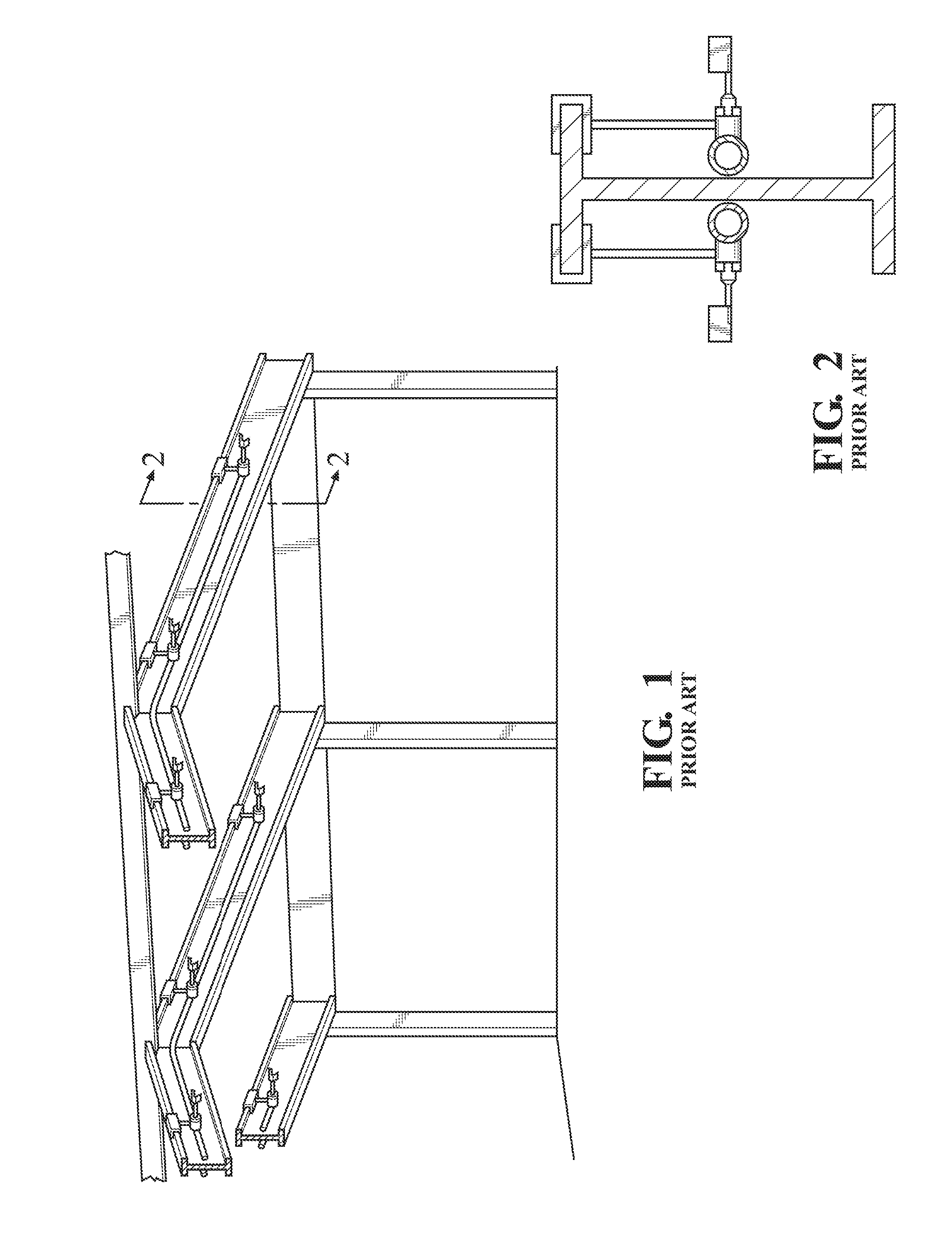
Despite their ability to discharge a greater water density, side-discharge sprinklers cannot be used in open surround conditions (i.e., located in the middle space between two structural beams (or girders, trusses, etc.) due to their inherent directional discharge patterns.
Furthermore, side-discharge sprinklers cannot be positioned near one another due to the aforementioned cold soldering problem.

Method used


Image

  • Multi-head array fire sprinkler system
  • Multi-head array fire sprinkler system
  • Multi-head array fire sprinkler system

Examples


Embodiment Construction

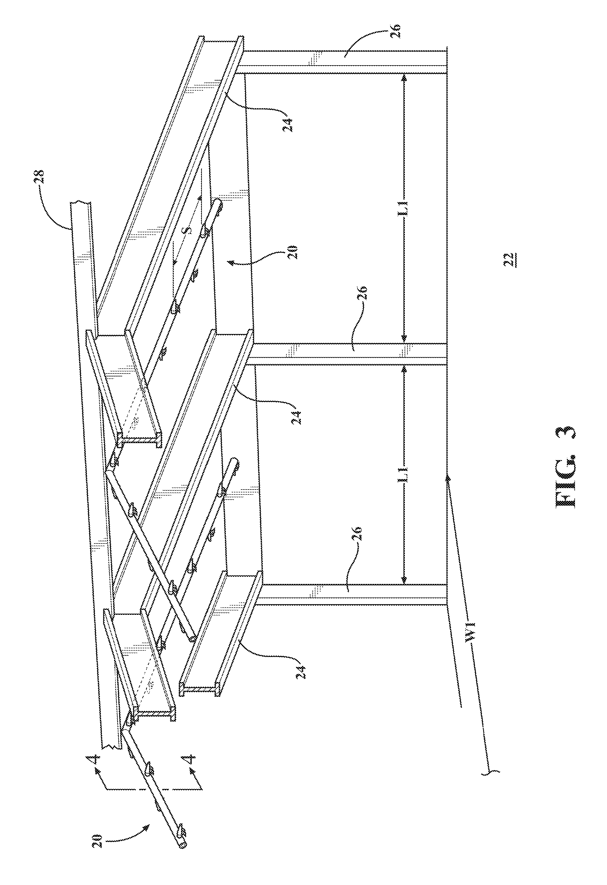
[0038]Referring to the figures, wherein like numerals indicate like or corresponding parts throughout the several views, a fire suppression system according to one exemplary expression of the present invention is generally shown at 20 in FIGS. 3-9. In FIG. 3, the fire suppression system 20 is shown located in the interior storage space of a building structure. The building structure may be a warehouse having a floor 22, and at least three beams 24 suspended over the floor 22. The beams 24 are preferably steel I-shaped rafters, but may be any suitable structural member made from any suitable material and shaped in any suitable manner. The beams 24 are typically arranged parallel to one another and spaced evenly apart by an interior bay length L1. In this example, the three beams 24 may be consider first, second and third beams24, with the second beam being disposed in between the first and third beams 24. Each beam 24 is supported by a pair of substantially vertical uprights or posts...


PUM


Abstract

A fire suppression system in which the water supply line (108) is fitted with repeating arrays of sprinkler heads (102, 106). Each array is substantially identical and is composed of two side-discharge sprinklers (106) and one vertical-discharge sprinkler (102). The side-discharge sprinklers (106) in each array are aimed so that their coverage areas point in opposite directions. The trigger (109) for the vertical-discharge sprinkler (102) has a lower activation temperature (Tv) than the activation temperatures (Th) of the side-discharge sprinklers (106) so that the vertical-discharge sprinkler (102) will activate earlier than either of the side-discharge sprinklers (106). The vertical-discharge sprinkler (102) may include a heat collector (104) to facilitate early activation of its trigger (109). The fire suppression system and method harness the working power of working of multiple orientations of fire sprinklers to produce, in effect, a super fire sprinkler system and method.

Description

CROSS REFERENCE TO RELATED APPLICATIONS[0001]This application claims priority to Provisional Patent Application No. 62 / 215,058 filed Sep. 7, 2015, and is a Continuation-in-Part of U.S. application Ser. No. 14 / 661,302 filed Mar. 18, 2015, which claims priority to Provisional Patent Application No. 61 / 955,253 filed Mar. 19, 2014 and to Provisional Patent Application No. 62 / 019,527 filed Jul. 1, 2014, the entire disclosures of which are hereby incorporated by reference and relied upon.BACKGROUND OF THE INVENTION[0002]Field of the Invention[0003]The invention relates generally to methods and systems for extinguishing fires, and more particularly to sprinklers of such systems.[0004]Description of Related Art[0005]Fire suppression systems have been used in the United States to protect warehouses and factories for many years. In a fire suppression system, a fire sprinkler is positioned near the ceiling of a room where hot “ceiling jets” spread radially outward from a fire plume. When the t...

Claims


Application Information

Patent Timeline
Patent Type & Authority Applications(United States)
IPC IPC(8): A62C35/68B05B1/26A62C3/00A62C37/11
CPCA62C35/68A62C3/002B05B1/267A62C37/11A62C31/02A62C35/64A62C37/12
Inventor PIGEON, JEFFREY J.
Owner FIREBIRD SPRINKLER COMPANY
Learn More