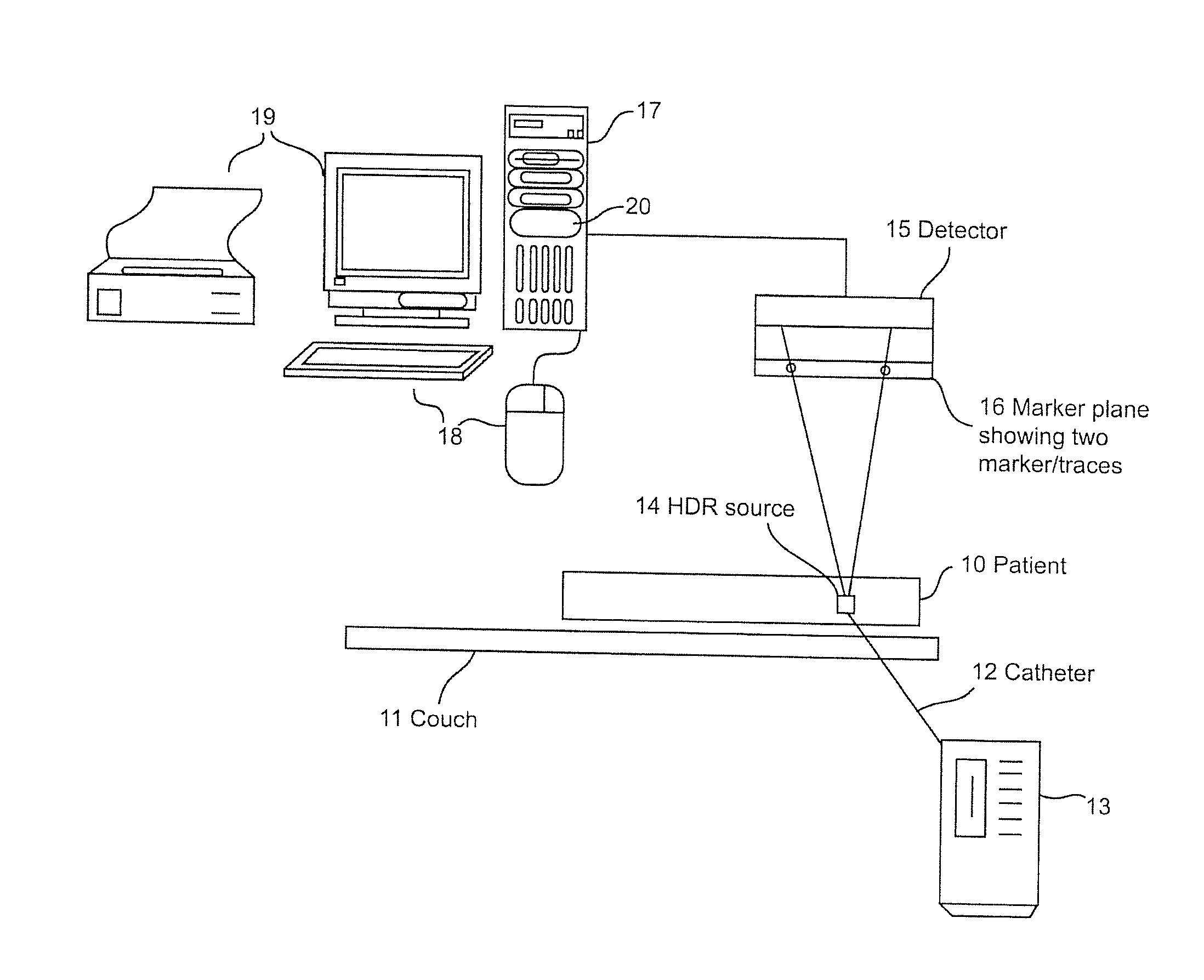
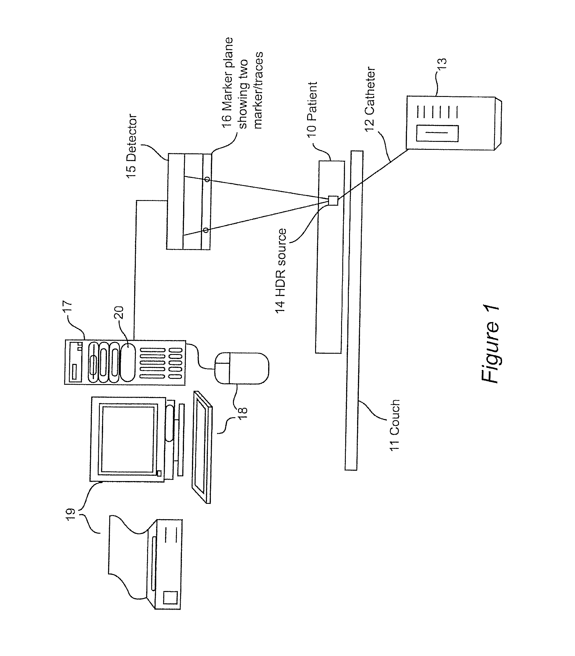
3D Tracking of an HDR Source Using a Flat Panel Detector
a technology of 3d tracking and detector, applied in the direction of instruments, image enhancement, therapy, etc., can solve the problems of exposing the patient to a double dose of radiation, difficult to evaluate whether the treatment is or has been delivered as planned, and complex problem of establishing a correspondence between a detection coordinate system and a plan coordinate system
- Summary
- Abstract
- Description
- Claims
- Application Information
AI Technical Summary
Benefits of technology
Problems solved by technology
Method used
Image

Examples
Embodiment Construction
[0035]The following description of the exemplary embodiments refers to the accompanying drawings. The following embodiments are discussed, for simplicity, with regard to the terminology and structure of a brachytherapy treatment methodology. Reference throughout the specification to “one embodiment” or “an embodiment” means that a particular feature, structure, or characteristic described in connection with an embodiment is included in at least one embodiment of the present invention. Thus, the appearance of the phrases “in one embodiment” or “in an embodiment” in various places throughout the specification is not necessarily all referring to the same embodiment. Further, the particular features, structures or characteristics may be combined in any suitable manner in one or more embodiments.
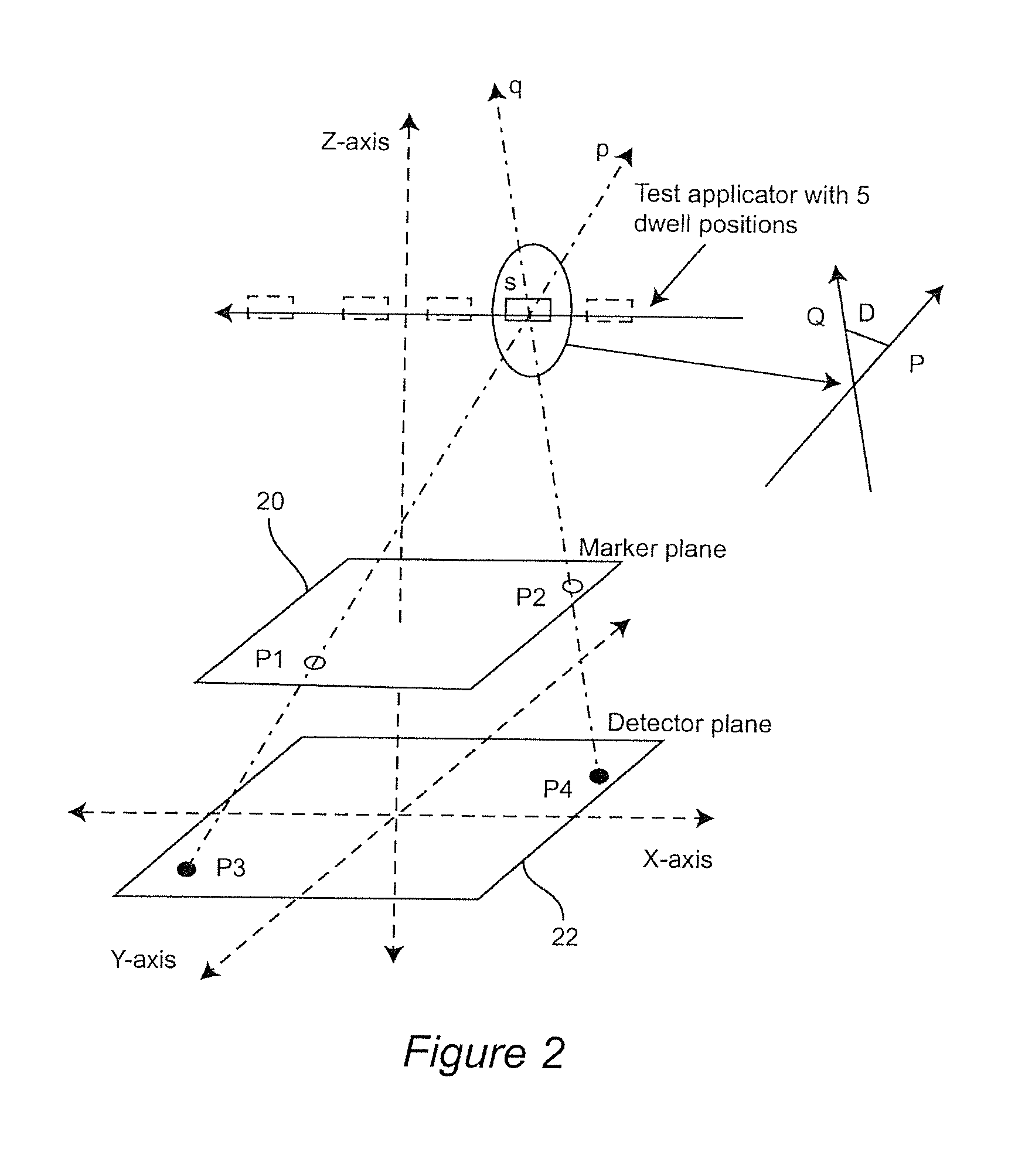
[0036]In the conventional X-ray, the patient's body is the unknown and the source is known. In the present invention, the source position is unknown and the markers' positions and sizes are known...
PUM
 Abstract
Description
Claims
Application Information
 - R&D
- Intellectual Property
- Life Sciences
- Materials
- Tech Scout
- Unparalleled Data Quality
- Higher Quality Content
- 60% Fewer Hallucinations
Browse by: Latest US Patents, China's latest patents, Technical Efficacy Thesaurus, Application Domain, Technology Topic, Popular Technical Reports.
© 2025 PatSnap. All rights reserved.Legal|Privacy policy|Modern Slavery Act Transparency Statement|Sitemap|About US| Contact US: help@patsnap.com