
Toothbrush for oral cavity position detection

a technology for teeth and electric toothbrushes, which is applied in the field of detecting the position of teeth in the oral cavity of electric toothbrushes, can solve the problems of difficult for users to find the right balance, gum irritation, gum recession, etc., and achieve the effect of accurately measuring the typical brushing force, cost and simplicity, and improving the overall detection accuracy

Active Publication Date: 2016-12-29
BRAUN GMBH
View PDF5 Cites 25 Cited by
  • Summary
  • Abstract
  • Description
  • Claims
  • Application Information

AI Technical Summary

Benefits of technology

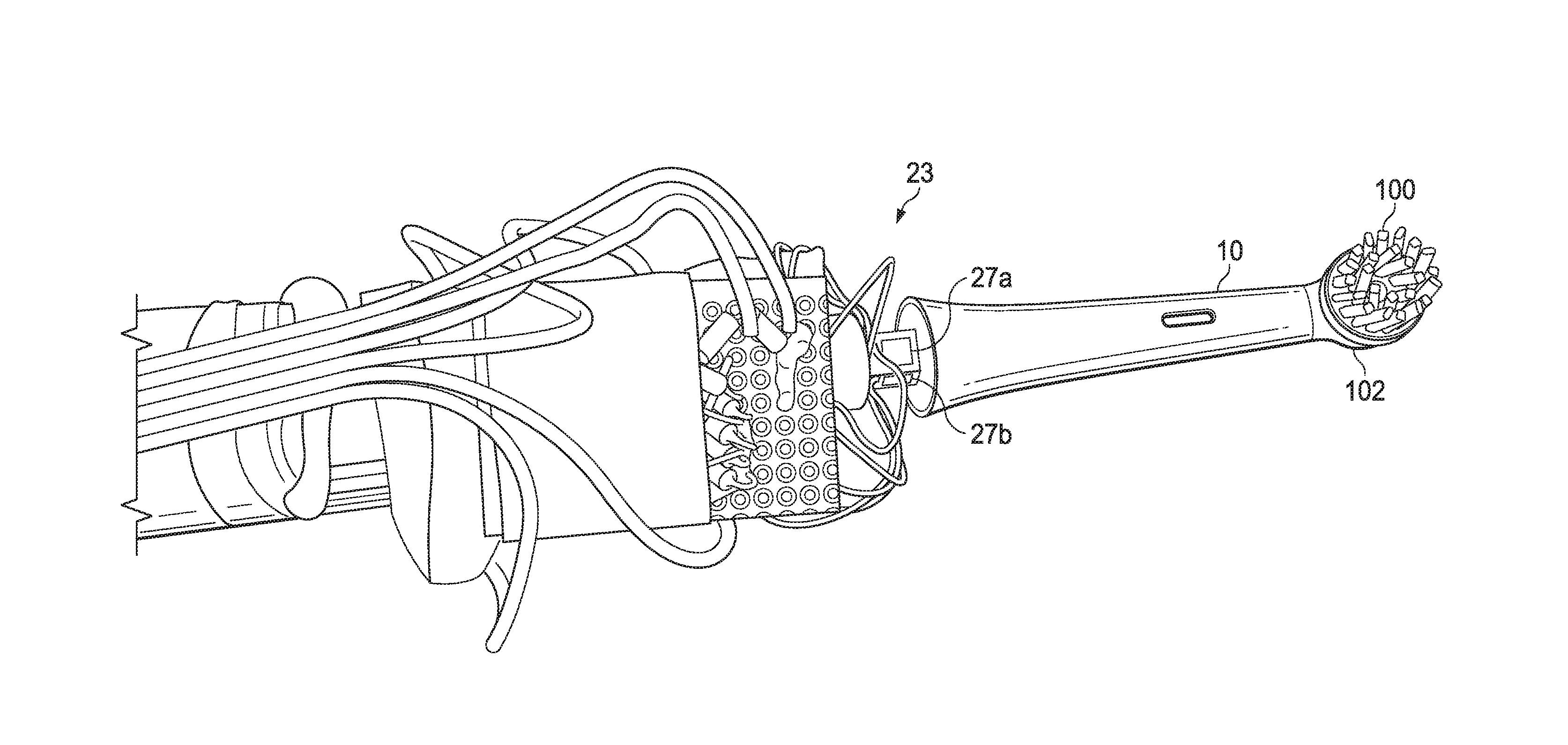
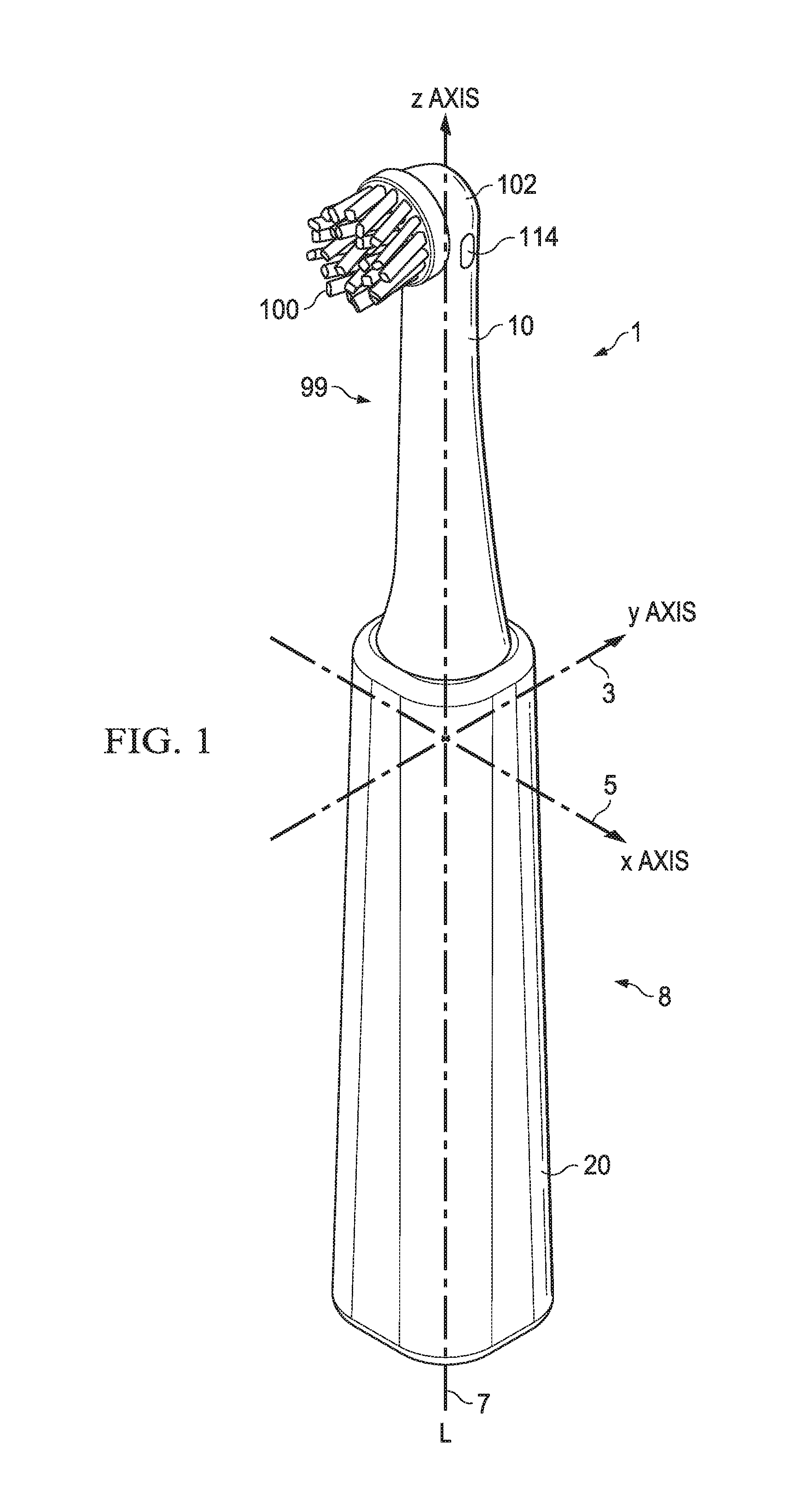
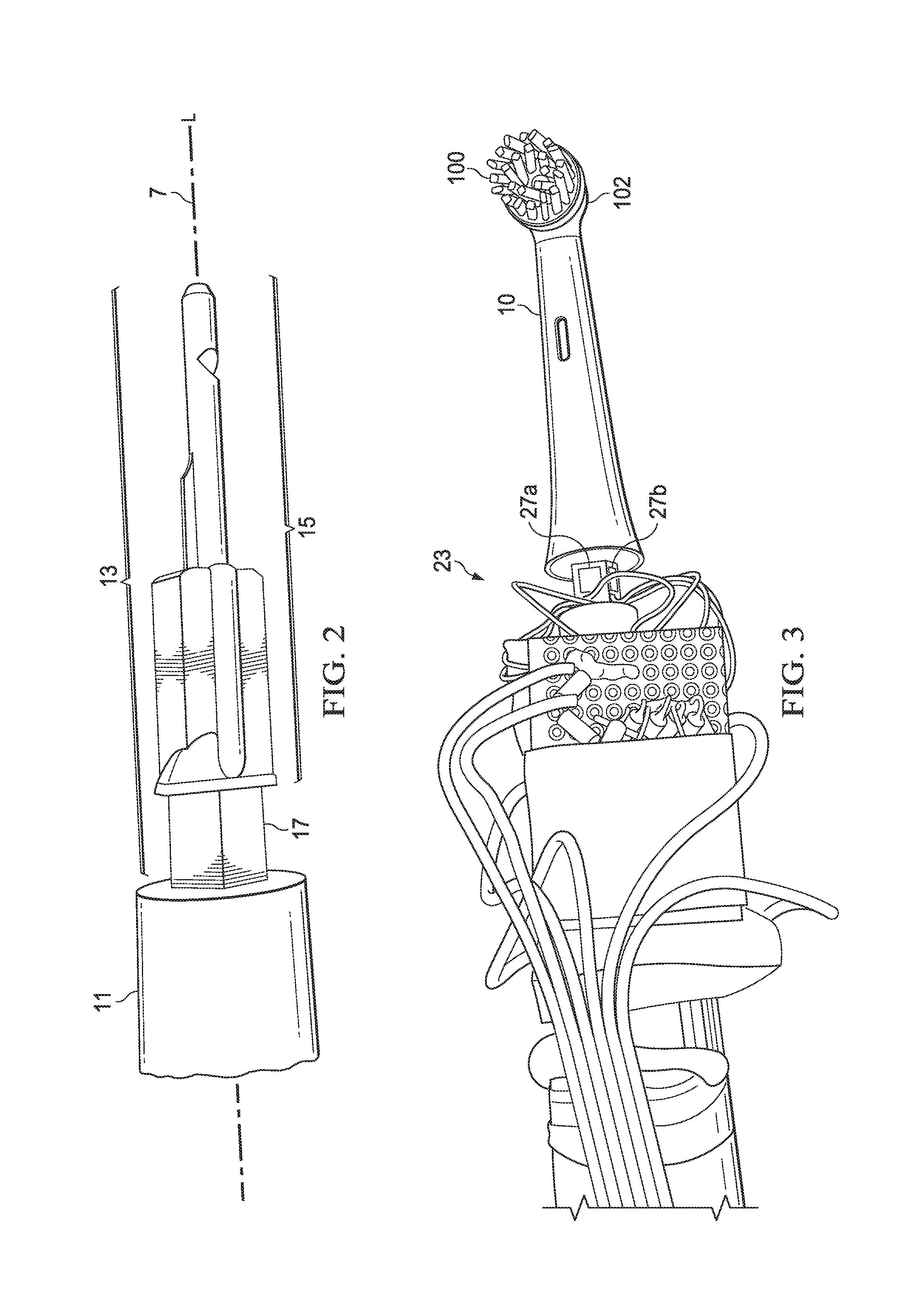
The present invention relates to an electric toothbrush handle that uses 3-axis force sensor data to provide user feedback on brushing force sufficiency or insufficiency. This allows users to find the right balance between not enough brushing force to enable cleaning but too much force resulting in gum irritation, gum recession, or even tooth enamel abrasion. The use of the 3-axis force sensor data provides the advantage of providing user feedback on the brushing force sufficiency or insufficiency. The electric toothbrush handle is designed to be cost-effective and easy to use. The receiver body is elastically deformable relative to the handle body, allowing for accurate position detection while brushing. The handle body contains an electric motor, a drive shaft, and a 3-axis force sensor, which is connected to the base of the handle. The cross sectional area of the base is important for accurate position detection, and the material used should not have bending properties changing too much with temperature and over time. The toothbrush also includes an accelerometer and gyroscope, contained within the handle body, to further improve oral cavity position detection during toothbrush operation.

Problems solved by technology

Indeed there is a need to balance between not enough brushing force to enable cleaning but too much force resulting in gum irritation, gum recession, or even tooth enamel abrasion.
It is often difficult for users to find the right balance.

Method used


Image

  • Toothbrush for oral cavity position detection
  • Toothbrush for oral cavity position detection
  • Toothbrush for oral cavity position detection

Examples


example 1

[0074]The following examples are provided using an electric toothbrush of the present invention. Reference is made to FIG. 6, and the 18 tooth zones (i.e., a-r). The electric toothbrush of the example has a head wherein the bristles are orthogonal to the longitudinal access. In example 1, the head of the electric toothbrush is inserted into the mouth as indicated in FIG. 7a, and the brushing operation is started in so called tooth zone j (out of 18 tooth zones). FIG. 7b shows the direction of the forces applied by the cheek on the head of the replaceable toothbrush head. The user has to push the cheek away with the head to move to the left part of the mouth, creating a normal bending force on the refill in the right direction as illustrated in FIG. 7b. The next step is moving the head down to reach zone j (and not zone a). This creates a lateral bending force going up. The combination of this 3-axis force sensor data coupled with the 3-axis accelerometer and gyroscope data indicate ...

example 2

[0075]Example 2 illustrates when a user starts in tooth zone k. When a user starts in tooth zone k, the cheek or the impact on the teeth will apply a little force on the refill in the direction shown in FIG. 8. Because a lateral bending force is detected, no normal force from the cheek and also 3-axis accelerometer and gyroscope data indicating the bristles are facing down, the starting oral cavity position is tooth zone k.


PUM


Abstract

A toothbrush handle for providing oral cavity position detection during operation includes a handle body having a longitudinal axis, a receiver body elastically deformable relative to the longitudinal axis, and a three-axis force sensor that is operatively connected to the base portion and configured to obtain three-axis force data for oral cavity position detection during operation.

Description

FIELD OF THE INVENTION[0001]The present invention is directed to detecting oral cavity positions of an electric toothbrush during operation.BACKGROUND OF THE INVENTION[0002]Maintaining good oral hygiene is important for oral health and even overall well-being. Proper and regular tooth brushing is a basic and important part of an oral care regimen. Various toothbrushes, including electric toothbrushes, have been developed to facilitate effective tooth brushing. Researchers have continuously tried to improve the brushing quality, for example, by optimizing the brushing head, increasing the head rotation frequency, designing new cleaning techniques such as by way of ultrasound. Although some of these attempts have been successful in theory and even endorsed by dentists, high brushing quality has not been achieved in practice by many consumers. There are several explanations proposed. For example, at least one study reports that an adult brushes on average for 46 seconds while the recom...

Claims


Application Information

Patent Timeline
Patent Type & Authority Applications(United States)
IPC IPC(8): A61B5/00A61C17/16A46B15/00A46B9/04A46B5/00A61B5/053A61C19/04
CPCA61B5/4547A61B5/0002A61B5/7246A61B5/486A61B5/0534A61C17/16A61B2562/0219A46B9/04A46B5/0095A46B15/0008A46B5/0025A61B2090/064A61B2562/0261A61C19/04A46B15/0006A46B15/0012A61B5/002A61B5/053A61B5/6887A61C17/221A61C17/222A61B2505/07A46B2200/1066
Inventor VETTER, INGOHALBACH, ALEXANDRE ANDRE
Owner BRAUN GMBH
Learn More