
Vehicle control

a vehicle control and steering wheel technology, applied in the direction of driver input parameters, non-deflectable wheel steering, external condition input parameters, etc., can solve the problems of driver feedback, various limitations of the approach, and the inability to provide driver feedback

Inactive Publication Date: 2007-08-28
RICARDO UK LTD
View PDF17 Cites 63 Cited by
  • Summary
  • Abstract
  • Description
  • Claims
  • Application Information

AI Technical Summary

Benefits of technology

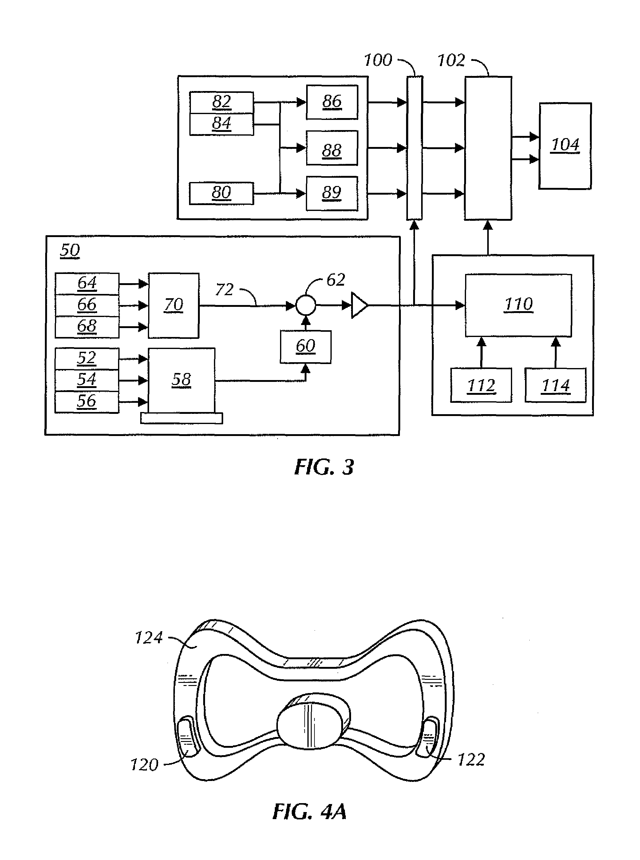
[0018]The system is enhanced by using external information for example the use of global positioning system (GPS) to assess vehicle slip in conjunction with measurements of yaw rate and acceleration and electronic compasses as multiple inputs to Kalman filters. The system also provides intelligent demand interpretation; for example if the driver demand exceeds possible vehicle performance then the system will provide the best comparable performance. Yet further, because the system is able to assess instantaneous vehicle performance it can provide feedback to the driver through the vehicle—for example through the steering wheel—such that the driver will know how the vehicle is performing and for example whether a limit condition is being approached.
[0020]The system also allows predictive control such that the sub-system can send to the supervisor predicted local conditions allowing yet further integration of the sub-systems to provide optimised vehicle performance. Similarly the supervisor controls the sub-system not only by sending basic set points but also by sending an operating envelope to the sub-system such that if certain conditions are met the sub-system is instructed to carry out appropriate steps in response. This capability is especially useful in the event of communications failure between the supervisor and sub-systems, allowing the sub-systems to continue to function using the estimate of preferred actions from the supervisor prior to such communications failure.

Problems solved by technology

However in many conventional systems the different elements are controlled by distributed autonomous controllers giving rise to significant conflicts.
This approach has various limitations.
Furthermore the driver is not provided with feedback as to the effect of the inputs he is providing and whether he is approaching a limit condition.
As a result driver demand may not be met, or the driver may not be able to detect this which is unsatisfactory to the driver.
Yet further known systems are not able to fully determine the current vehicle state including parameters that significantly affect performance and safety, such as vehicle slip angle, further degrading their performance.
A further problem with known systems is that different driver inputs for example steering and accelerator pedal may present conflicting messages.
Such conflicting signals can be misread by existing systems giving rise to significant performance and safety concerns.
Yet a further problem with known systems in encountered in the existing control hierarchy model.
This is especially a problem in the automobile sector where many of the sub-system actuators are proprietary to different manufacturers such that conflict can often arise.
As a result the performance of the vehicle as a whole is compromised because the supervisor does not have fully integrated control.
Yet further the supervisor in conventional systems simply sends out set points to be met by each actuator which is inflexible, requires constant update and may also provide risk of failure modes.

Method used


Image

  • Vehicle control
  • Vehicle control
  • Vehicle control

Examples


Embodiment Construction

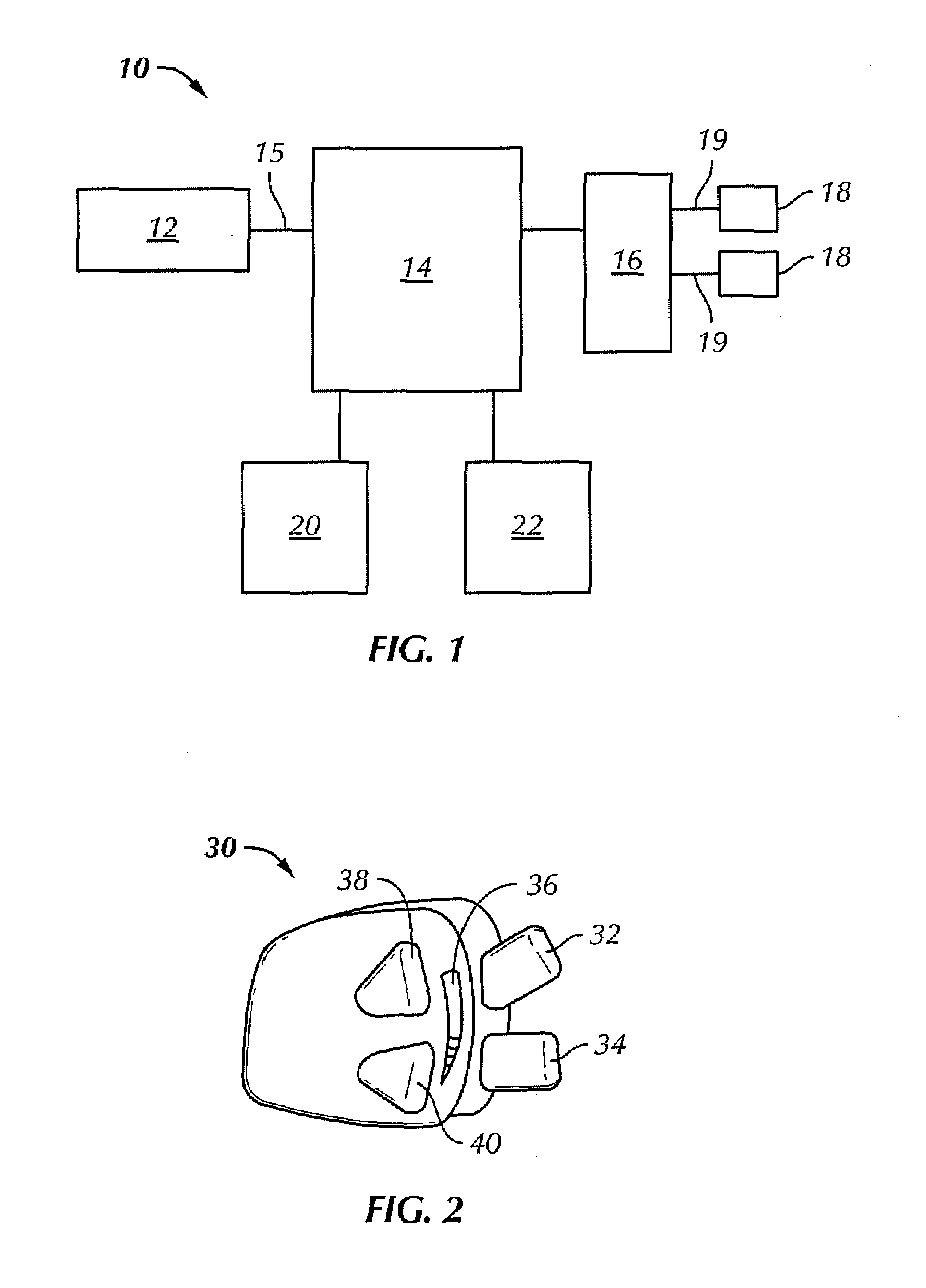
[0016]In overview the present invention provides a vehicle control system in which driver inputs such as steering wheel and accelerator pedal to the supervisor are effectively de-coupled to assess true driver demand for example in instances where the inputs are potentially conflicting. From this, vehicle output parameters can be derived such as the required vehicle slip or yaw rate.

[0017]The supervisor then controls vehicle sub-systems according to known techniques and provides appropriate set points to each sub-system such that the desired vehicle output parameters are achieved. As a result the system interprets and meets the driver demand providing for example a power oversteer capability.

[0018]The system is enhanced by using external information for example the use of global positioning system (GPS) to assess vehicle slip in conjunction with measurements of yaw rate and acceleration and electronic compasses as multiple inputs to Kalman filters. The system also provides intelligen...


PUM


Abstract

A vehicle control system includes at least one driver input, a supervisor and at least one sub-system controlled by the supervisor. The supervisor assesses the driver input to establish actual driver demand and controls the sub-systems accordingly. As a result intuitive driver demand is identified and met.

Description

FIELD OF THE INVENTION[0001]The invention relates to improvements in vehicle control.BACKGROUND OF THE INVENTION[0002]In conventional systems process for developing passive suspensions involve vehicle modelling and simulation to vary parameter values to achieve an acceptable compromise between competing vehicle attributes such as ride and handling within a given suspension working space. Controllable suspension elements (such as switchable dampers, controlled roll bars and variable spring elements) have been introduced to maintain the lateral force generating capability of the tyre contact patch. This is achieved by control of wheel camber, steer angle and normal loading and, generally speaking, controllable suspension elements are compatible with all systems which vary applied wheel torque since the systems are complementary. In a similar way, systems contributing to wheel torque (engine, transmission, active drive line) have been developed. However in many conventional systems the...

Claims


Application Information

Patent Timeline
Patent Type & Authority Patents(United States)
IPC IPC(8): B62D7/14G06F17/00B62D6/00B60T8/00B60T8/172B60T8/1755B60W10/00B60W10/04B60W30/18B60W40/08B60W50/00B60W50/02B60W50/06B62D113/00F02D29/00F02D29/02F16H61/02G06N3/00
CPCB60T8/172B60W30/188B60G2600/042B60G2600/1878B60G2600/1879B60G2800/702B60K2741/006B60T2210/36B60T2220/02B60W40/09B60W50/02B60W50/06B60W2050/0026B60W2050/0057B60W2540/30B60W2550/148B60W2550/402B60W2720/14B60W30/1819B60W2552/40B60W2556/50
Inventor WHEALS, JONATHAN CHARLESRAMSBOTTOM, MARK
Owner RICARDO UK LTD
Learn More