Pressure sensing element having an insulating layer with an increased height from the substrate towards the opening

a pressure sensor and insulating layer technology, applied in the field of pressure sensing elements and pressure sensors, can solve the problems difficult to demonstrate the desired level of initial detection sensitivity in the flat state, and the problem of so as to prevent short-circuiting in the initial state, and good initial detection sensitivity

Active Publication Date: 2016-12-15
NIPPON MEKTRON LTD
View PDF0 Cites 9 Cited by
  • Summary
  • Abstract
  • Description
  • Claims
  • Application Information

AI Technical Summary

Benefits of technology

This invention relates to a pressure sensing element that has excellent sensitivity both in its flat and bent states, and prevents short-circuiting during initial use. This makes it suitable for use in a wide range of applications and ensures electrical reliability. The method of manufacturing the pressure sensing element is easy to follow.

Problems solved by technology

The conventional pressure sensors have, however, suffered from the problems below.
The conventional pressure sensors having such small gaps, when mounted to the surface of an article other than flat surface and used in a flexible mode, has been anticipated to cause short-circuiting in the initial state, since the board bends to make the gap narrower than in the flat state.
On the other hand, the conventional pressure sensor, if configured to have the gap widened enough to prevent short-circuiting even in the bent state, will become difficult to demonstrate a desired level of initial detection sensitivity in the flat state.
In short, the conventional pressure sensors have been difficult to demonstrate good initial detection sensitivity both in the flat state and the bent state, as well as to prevent short-circuiting in the initial state.
The conventional pressure sensors have therefore not been suitable enough for use in recent wide variety of fields.

Method used


Image

  • Pressure sensing element having an insulating layer with an increased height from the substrate towards the opening
  • Pressure sensing element having an insulating layer with an increased height from the substrate towards the opening
  • Pressure sensing element having an insulating layer with an increased height from the substrate towards the opening

Examples


first embodiment

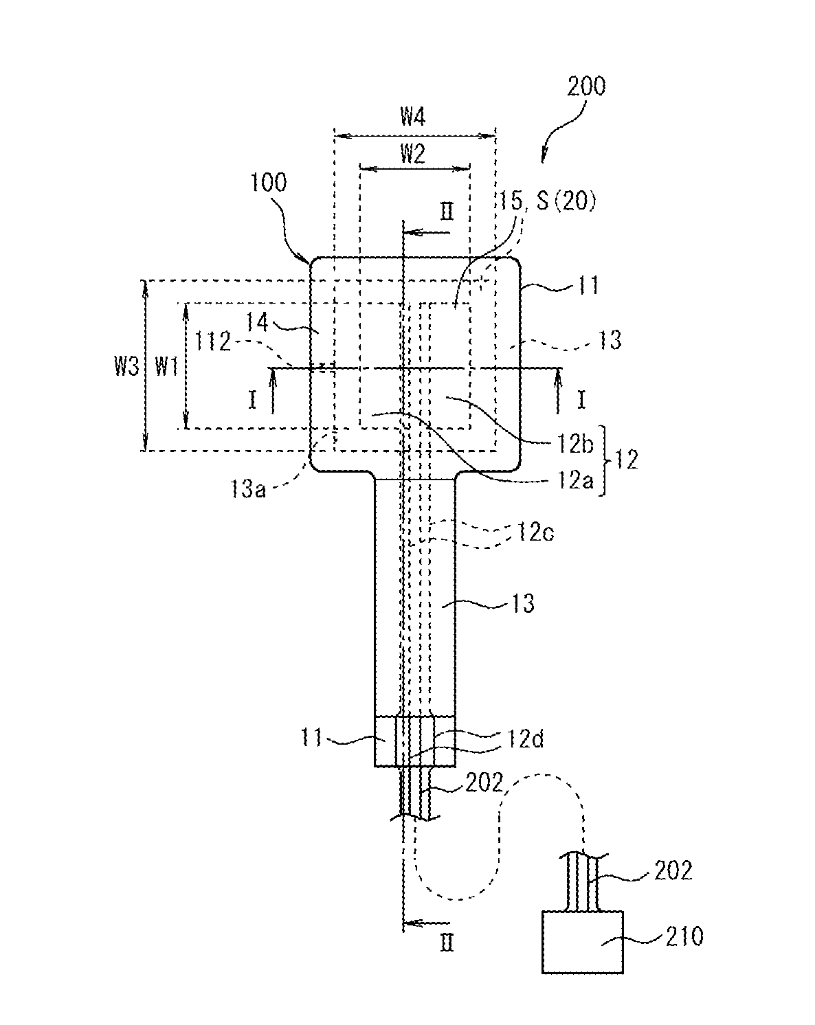
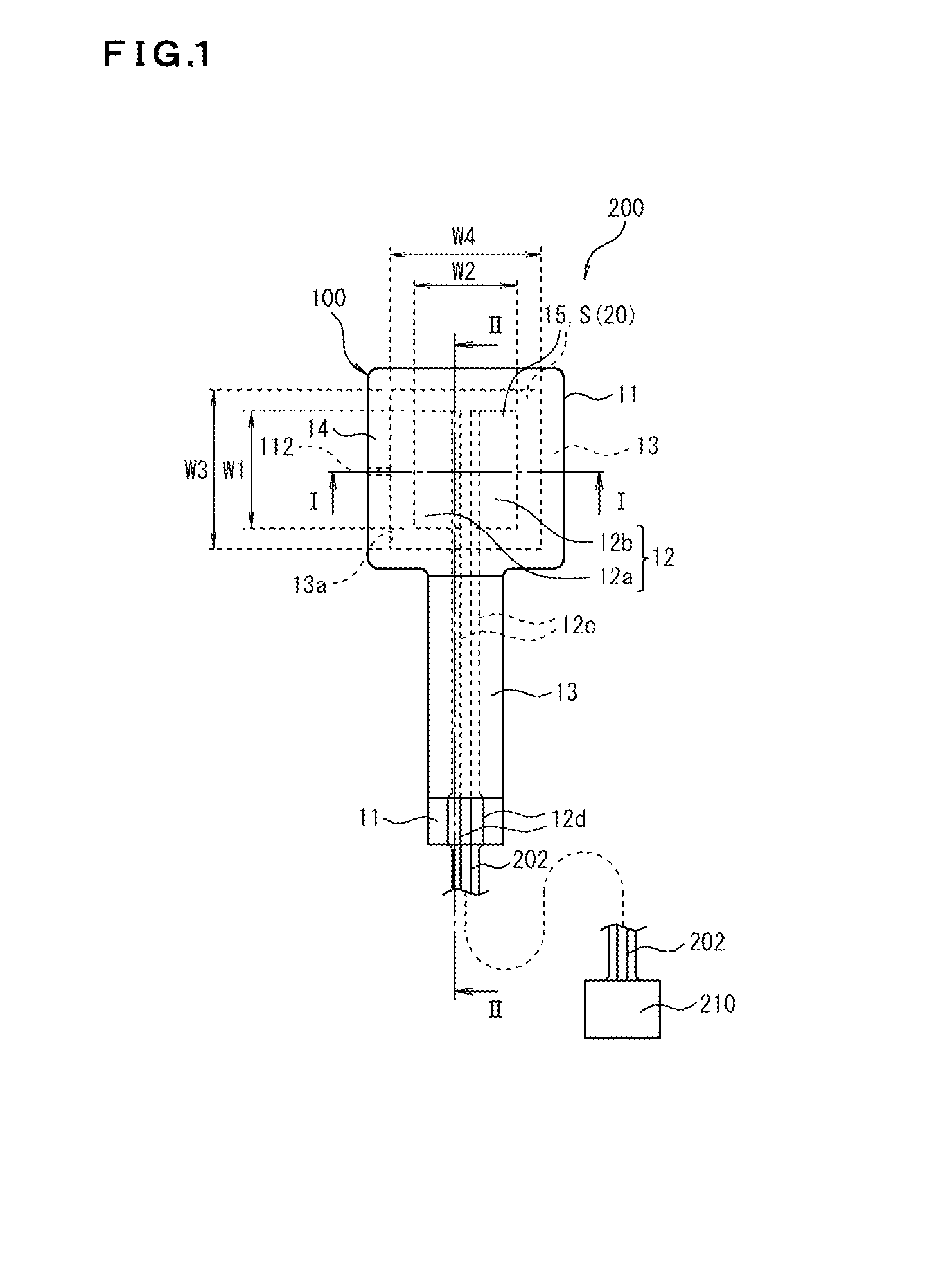
[0040]A pressure sensing element 100 of the first embodiment and a pressure sensor 200 will be explained below, referring to FIG. 1 to FIG. 4. FIG. 1 is a plan view illustrating the pressure sensor 200 according to a first embodiment of this invention. FIG. 2A is a cross sectional view taken along line I-I in FIG. 1, and FIG. 2B is a cross sectional view taken along line II-II in FIG. 1. FIG. 3A to FIG. 3C are plan views illustrating a modified example of a sensor electrode 12. FIG. 4 is an explanatory drawing explaining the initial detection sensitivity and dynamic range of the pressure sensing element 100 of the first embodiment. A curve 110 illustrated in FIG. 4 merely indicates a tendency of the dynamic range of the pressure sensing element 100, without limiting this invention.

[0041]The pressure sensing element 100 of this embodiment is a single-channel type element configured by a pressure sensor part 15 having a single sensor electrode 12 and a pressure sensing film 14 opposed...

second embodiment

[0115]Next, a pressure sensing element 300 and a pressure sensor 400 according to a second embodiment of this invention will be explained referring to FIG. 5 to FIG. 8, and occasionally referring to FIG. 9D. The pressure sensing element 300 of this embodiment is different from the pressure sensing element 100 of the first embodiment, in that it has a plurality of sensor electrodes 12. The pressure sensor 400 is different from the pressure sensor 200 in that it has a pressure sensing element 300 in place of the pressure sensing element 100.

[0116]FIG. 5 is a plan view illustrating the pressure sensing element 300 according to the second embodiment of this invention. FIG. 6A is a partially enlarged view of part “A” in FIG. 5, and FIG. 6B is a partially enlarged view of part “B” in FIG. 5. FIG. 7A and FIG. 7B are partially enlarged views of part “A” in FIG. 5, from which the pressure sensing film 14 has been removed. FIG. 8 is a perspective view illustrating a pressure sensor 400 having...

third embodiment

[0133]Next, as a third embodiment of this invention, the method of manufacturing a pressure sensing element of this invention will be explained referring to FIG. 9A, FIG. 9B, FIG. 9C, FIG. 9D and FIG. 10. Although this embodiment will explain a method of manufacturing the pressure sensing element 300, the description may conveniently be referred to as describing the method of manufacturing a single-channel pressure sensing element 100 having only one pressure sensitive part.

[0134]FIG. 9A to FIG. 9D are an explanatory drawing explaining steps of manufacturing the pressure sensing element according to the third embodiment of this invention. FIG. 9A to FIG. 9D illustrate a cross sectional view taken at a portion where the sensor electrodes 12 are formed, in the direction of normal line of the support substrate 11. FIG. 9A illustrates a step of coating of a photo-sensitive coating material 174 by screen printing over the support substrate 11 having sensor electrodes 12 provided thereto....


PUM


Abstract

A pressure sensing element (100) includes a support substrate (11); a sensor electrode (12) supported by the support substrate (11); a pressure sensing film (14) functionalized to be electro-conductive, at least in a portion thereof faced to the sensor electrode (12); and an insulating layer (13) which keeps the sensor electrode (12) and the pressure sensing film (14) apart from each other by a predetermined distance A, and has formed therein an opening (20) in which the sensor electrode (12) is exposed to the pressure sensing film (14), the insulating layer (13) having an aperture wall (13b) which partitions the opening (20), and an aperture end (top aperture end (13a)) faced to the pressure sensing film (14), and the insulating layer (13) being increased in height, measured from the support substrate (11), continuously towards the opening (20).

Description

TECHNICAL FIELD[0001]This invention relates to a pressure sensing element, a pressure sensor, and a method of manufacturing a pressure sensing element.BACKGROUND ART[0002]In recent years, tactile sensing has rapidly been expanding its presence in the fields of medical treatment, welfare, robot, virtual reality, and so forth.[0003]In the automotive field, for example, it has been general to embed a pressure sensing element into a seat. This is aimed at prompting a passenger who gets on a vehicle and sits on the seat to fasten a seat belt. More specifically, upon sitting of the passenger on the vehicle seat, a predetermined level or larger load (weight) is applied to the pressure sensing element. Accordingly, a pressure sensor equipped with the pressure sensing element senses the presence of the passenger, and prompts him or her to fasten the seat belt.[0004]Other expected applications of the pressure sensor include those in medical or nursing field.[0005]More specifically, for exampl...

Claims


Application Information

Patent Timeline
IPC IPC(8): G01L1/22A61B5/00
CPCG01L1/2287A61B2562/12A61B2562/0247A61B5/447G01L5/00G01L5/228G01L1/205A61B2562/164A61B2562/046
Inventor IWASE, MASAYUKITOYAMA, KEIZOOZAKI, KAZUYUKIOHDATE, HIROKAZUKIMURA, TAISUKETOYOSHIMA, RYOICHI
Owner NIPPON MEKTRON LTD
Why Eureka
Try Eureka