Rotating electric machine
a technology of rotating electric machines and rotating shafts, which is applied in the direction of synchronous motors, magnetic circuit rotating parts, magnetic circuit shapes/forms/construction, etc., can solve the problems of limiting the characteristics and affecting the operation of rotating electric machines. , to achieve the effect of increasing the number of torque-acting surfaces of rotating electric machines, high output torque, and high output torqu
- Summary
- Abstract
- Description
- Claims
- Application Information
AI Technical Summary
Benefits of technology
Problems solved by technology
Method used
Image

Examples
first embodiment
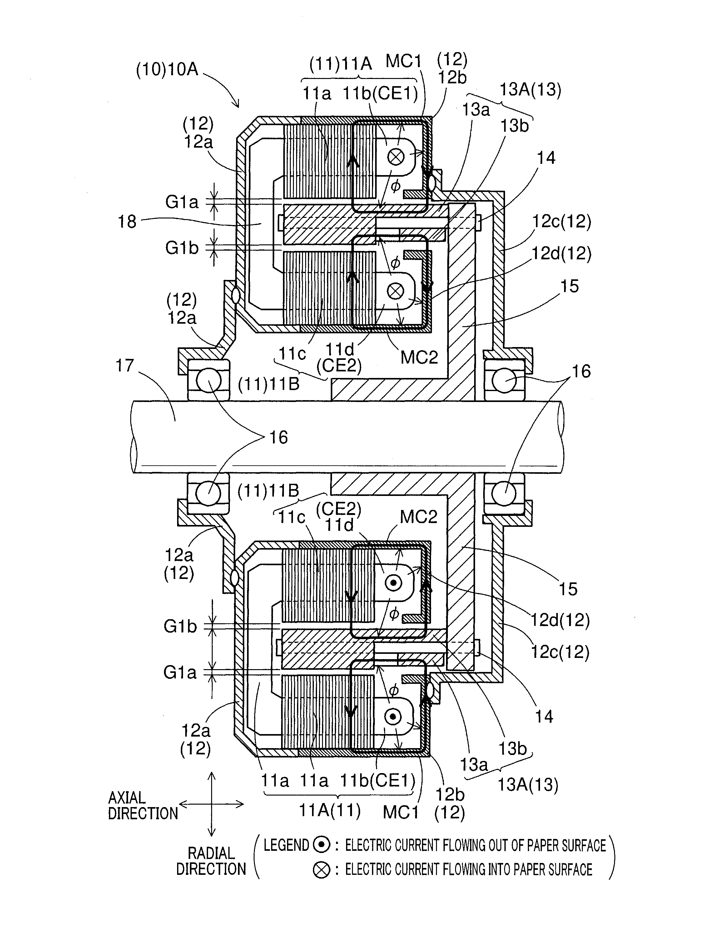
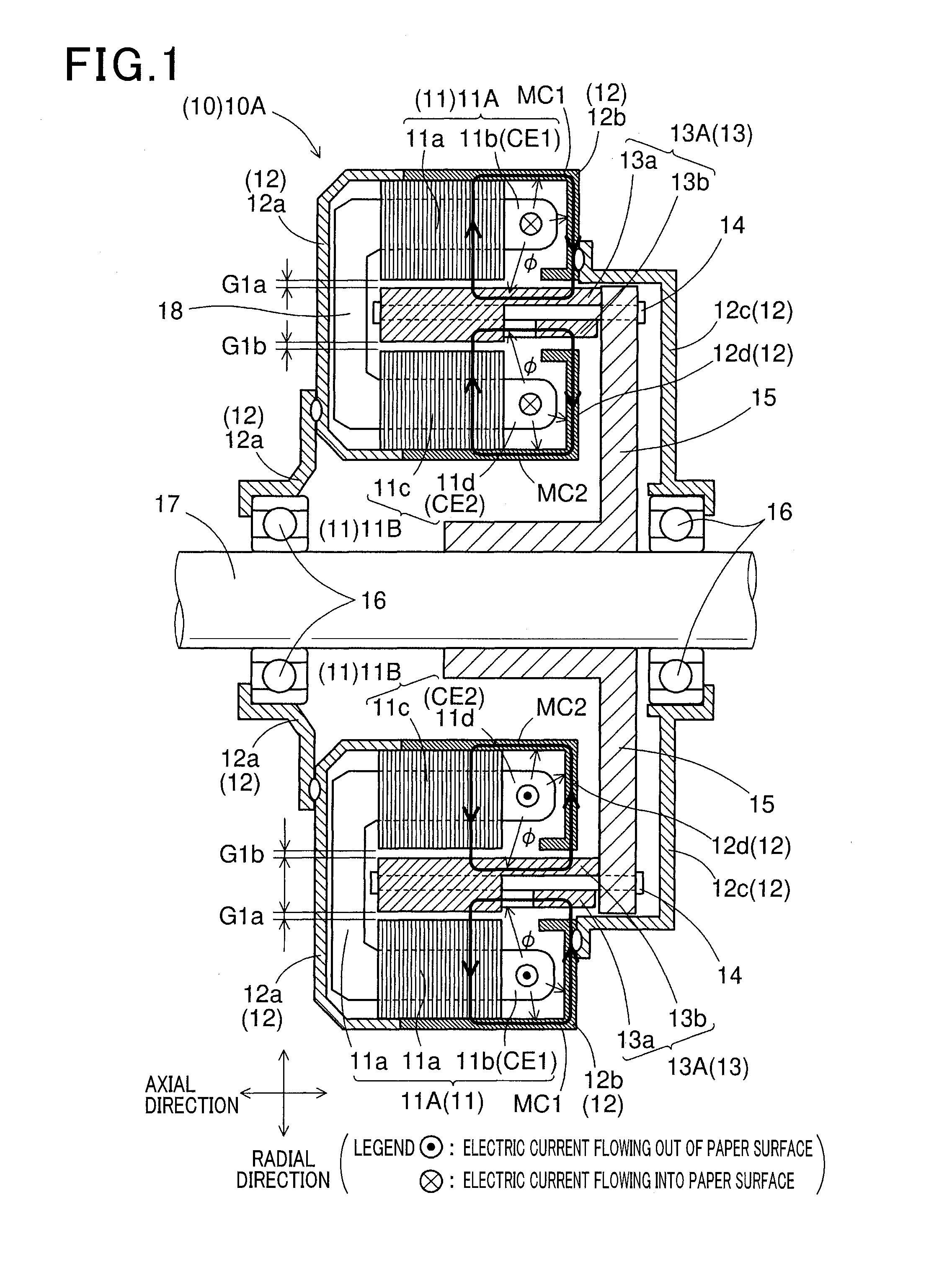
[0040]FIG. 1 shows the overall configuration of a double-stator rotating electric machine 10A according to a first embodiment. The double-stator rotating electric machine 10A is an example of a rotating electric machine 10 according to the present invention.
[0041]In addition, the rotating electric machine 10 according to the present invention may be an electric motor, an electric generator or a motor-generator that selectively functions either as an electric motor or as an electric generator.
[0042]As shown in FIG. 1, the rotating electric machine 10A includes an outer armature (or stator) 11A, an inner armature (or stator) 11B, a rotor 13A, a pair of bearings 16 and a rotating shaft 17, all of which are received in a housing 12.
[0043]In addition, the upper half of FIG. 1 shows a cross section of an upper half of the rotating electric machine 10A which is taken to include a cross section of a first ring member 13a; the lower half of FIG. 1 shows a cross section of a lower half of the...
second embodiment
[0078]A rotating electric machine 10B according to a second embodiment will be described with reference to FIGS. 6-8. The rotating electric machine 10B is another example of the rotating electric machine 10 according to the present invention.
[0079]The rotating electric machine 10B according to the present embodiment has a configuration similar to that of the rotating electric machine 10A according to the first embodiment. Accordingly, for the sake of avoiding redundancy, the differences of the rotating electric machine 10B from the rotating electric machine 10A will be mainly described.
[0080]In the first embodiment, the rotating electric machine 10A is configured as a double-stator rotating electric machine. In comparison, in the present embodiment, the rotating electric machine 10B is configured as a double-rotor rotating electric machine.
[0081]Specifically, as shown in FIG. 6, the rotating electric machine 10B according to the present embodiment includes an armature (or stator) 11...
third embodiment
[0111]A winding example of a multi-phase coil and an electric power converter 20A according to a third embodiment will be described with reference to FIGS. 9-11. The winding example and the electric power converter 20A can be applied to both the rotating electric machines 10A and 10B according to the first and second embodiments.
[0112]In addition, the electric power converter 20A is an example of an electric power converter 20 according to the present invention. The electric power converter 20A may be either built in the rotating electric machines 10A and 10B or arranged outside and electrically connected with the rotating electric machines 10A and 10B.
[0113]As shown in FIG. 9, the multi-phase coil is comprised of a U-phase winding 11U, a V-phase winding 11V and a W-phase winding 11W. The multi-phase coil may be any of the outer and inner multi-phase coils 11b and 11d included in the rotating electric machine 10A according to the first embodiment (see FIG. 1) and the multi-phase coi...
PUM
 Abstract
Description
Claims
Application Information
 - R&D
- Intellectual Property
- Life Sciences
- Materials
- Tech Scout
- Unparalleled Data Quality
- Higher Quality Content
- 60% Fewer Hallucinations
Browse by: Latest US Patents, China's latest patents, Technical Efficacy Thesaurus, Application Domain, Technology Topic, Popular Technical Reports.
© 2025 PatSnap. All rights reserved.Legal|Privacy policy|Modern Slavery Act Transparency Statement|Sitemap|About US| Contact US: help@patsnap.com