
Scaffold-free 3D porous electrode and method of making a scaffold-free 3D porous electrode

a porous electrode, scaffold-free technology, applied in the direction of electrode manufacturing process, cell components, electrochemical generators, etc., can solve the problems of low fraction of electrochemically active materials, low rate performance, and high metal mass

Active Publication Date: 2016-12-01
THE BOARD OF TRUSTEES OF THE UNIV OF ILLINOIS
View PDF2 Cites 7 Cited by
  • Summary
  • Abstract
  • Description
  • Claims
  • Application Information

AI Technical Summary

Benefits of technology

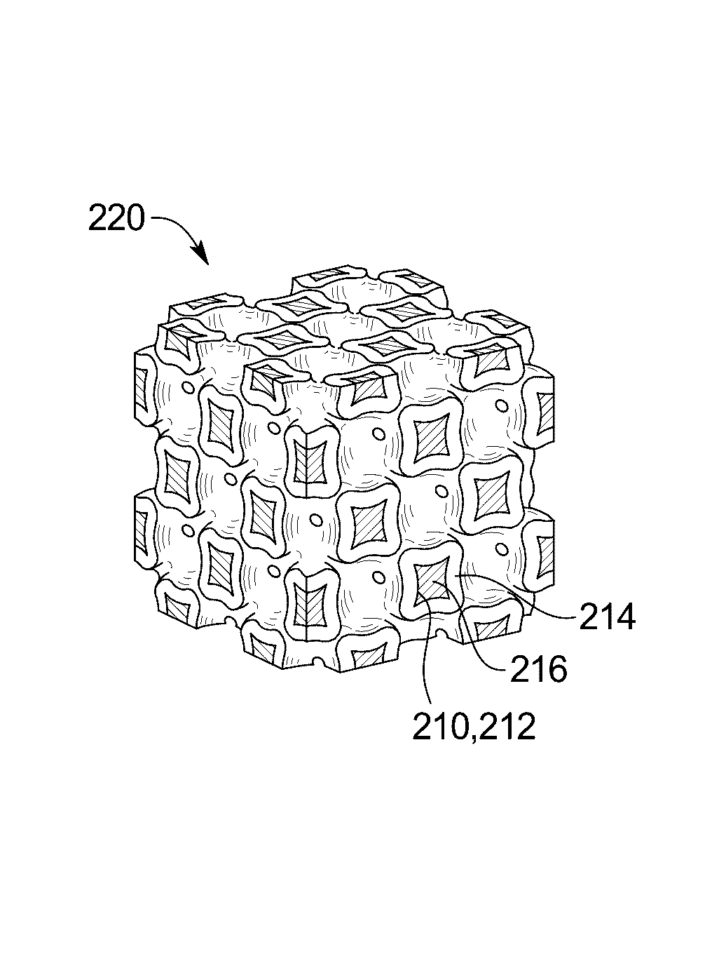
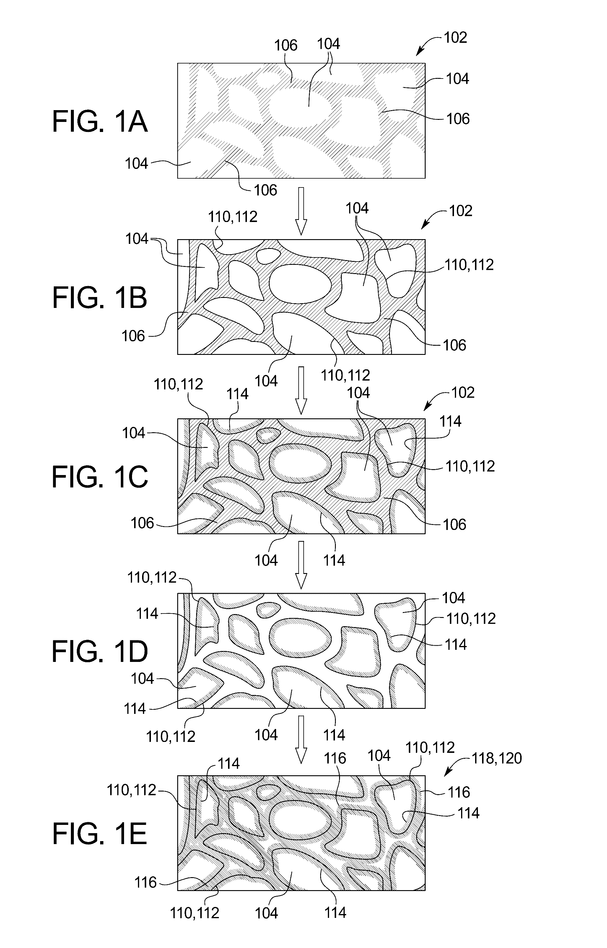
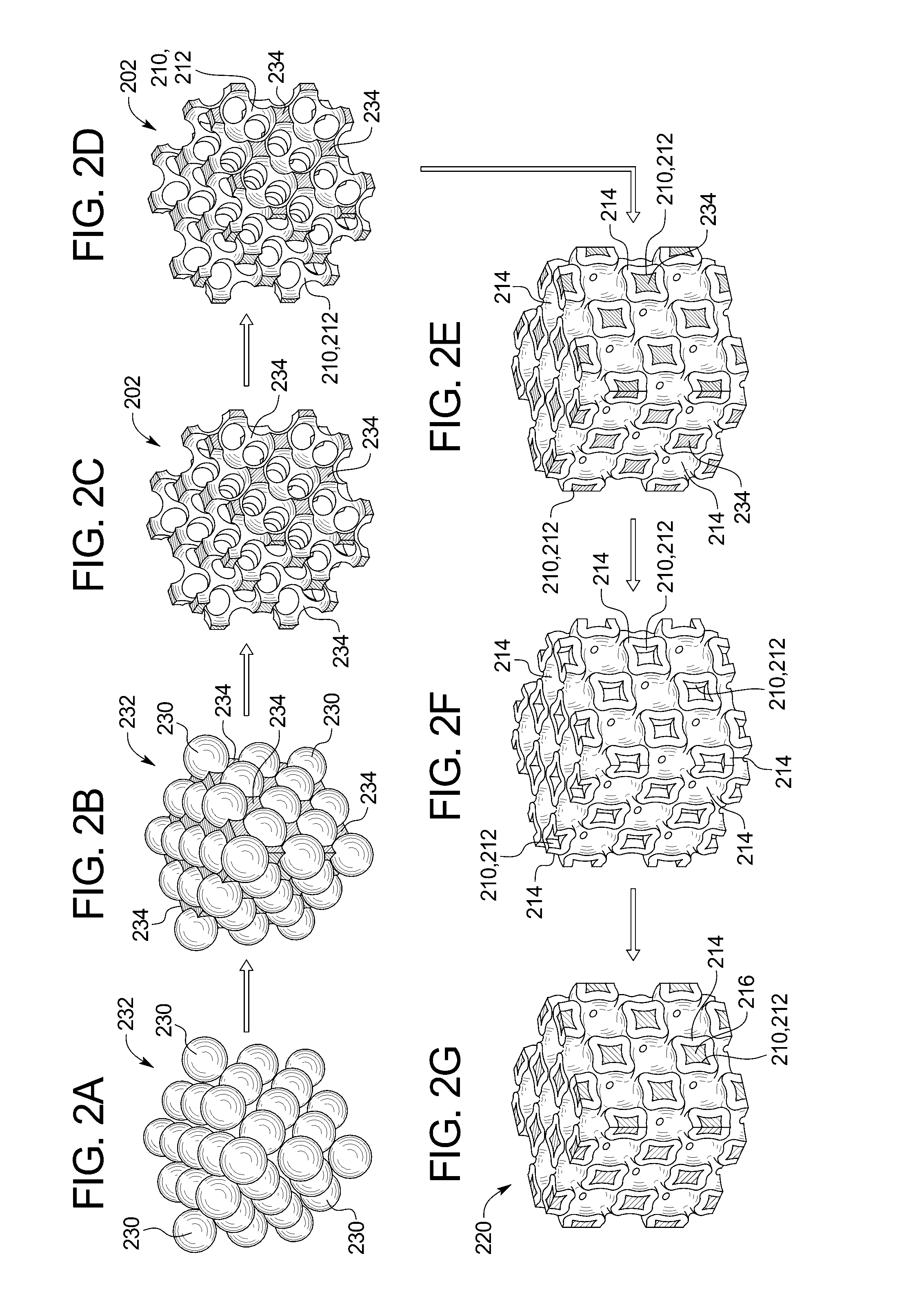
The patent text describes a new type of electrode that has a network of interconnected pores. The pores are surrounded by a multilayer film that includes a layer of electrochemically active material, one or more layers of graphene, and another layer of electrochemically active material. The method of making this electrode involves depositing one or more monolayers of graphene onto a porous scaffold to form a graphene coating on the scaffold, and then depositing a first layer of electrochemically active material onto the graphene coating. The scaffold is then removed to expose the underside of the graphene coating, and a second layer of electrochemically active material is deposited onto the underside of the graphene coating, resulting in a scaffold-free 3D porous electrode. The technical effect of this electrode is that it has a high surface area, which allows for better contact with the electrochemically active materials, leading to improved performance of the electrode.

Problems solved by technology

However, if the ionic and electronic conductivity of the electrode is too low, the rate performance may suffer.
Electrodes have been fabricated that provide networks for fast Li ion and electron transport kinetics and short solid-state ion and electron diffusion lengths; however, the fraction of electrochemically active material has generally been lower than desired.
For example, in the case of metal foams employed as conductive scaffolds, the mass of the metal can be considerable, lowering the capacity on a full electrode basis.

Method used


Image

  • Scaffold-free 3D porous electrode and method of making a scaffold-free 3D porous electrode
  • Scaffold-free 3D porous electrode and method of making a scaffold-free 3D porous electrode
  • Scaffold-free 3D porous electrode and method of making a scaffold-free 3D porous electrode

Examples


examples

Fabrication of Scaffold-Free 3D Porous Cathode

[0039]Fabrication of Porous Scaffold Via Templating Process: Face-centered cubic lattices of polystyrene (PS) particles (“PS opals”) are used to fabricate porous conductive scaffolds in a templating process described previously (e.g., as described in U.S. Pat. No. 8,237,538, “Porous Battery Electrode for Rechargeable Battery and Method of Making the Electrode,” issued on Aug. 7, 2012, which is hereby incorporated by reference in its entirety), with the modifications noted below. Since PS opals are used as templates in this example, the porous conductive scaffolds may be referred to as “inverse opals,” or, more specifically, “Ni inverse opals” since the porous conductive scaffolds comprise electrodeposited nickel.

[0040]1 cm×2 cm, 0.25 mm thick tungsten foils (≧99.9% trace metals basis, Sigma-Aldrich) are employed as substrates. Before PS opal assembly, tungsten substrates are cleaned by sonication in acetone, ethanol, and Millipore water ...


PUM


Abstract

A scaffold-free 3D porous electrode comprises a network of interconnected pores, where each pore is surrounded by a multilayer film including a first layer of electrochemically active material, one or more monolayers of graphene on the first layer of electrochemically active material, and a second layer of electrochemically active material on the one or more monolayers of graphene. A method of making a scaffold-free 3D porous electrode includes depositing one or more monolayers of graphene onto a porous scaffold to form a graphene coating on the porous scaffold, and depositing a first layer of an electrochemically active material onto the graphene coating. The porous scaffold is removed to expose an underside of the graphene coating, and a second layer of the electrochemically active material is deposited onto the underside of the graphene coating, thereby forming the scaffold-free 3D porous electrode.

Description

RELATED APPLICATIONS[0001]The present patent document claims the benefit of priority under 35 U.S.C. §119(e) to U.S. Provisional Patent Application Ser. No. 62 / 166,602, filed on May 26, 2015, which is hereby incorporated by reference in its entirety.FEDERALLY SPONSORED RESEARCH OR DEVELOPMENT[0002]This invention was made with government support under contract number DE-FG02-07ER46471 awarded by the Department of Energy. The government has certain rights in the invention.TECHNICAL FIELD[0003]The present disclosure is related generally to energy storage technology and more specifically to rechargeable battery electrodes.BACKGROUND[0004]Demands for improvements in energy storage have been driven by needs ranging from portable electronics to vehicle electrification, with almost universally, a high energy density, a good cycle life, safety, and acceptable cost being required. Ideally, to achieve a high energy density, the volume fraction of electrochemically active materials in the elect...

Claims


Application Information

Patent Timeline
IPC IPC(8): H01M4/04H01M4/133H01M4/38H01M4/134H01M4/48H01M10/0525H01M4/131
CPCH01M4/0428H01M10/0525H01M4/133H01M4/131H01M2004/029H01M4/483H01M4/386H01M2004/021H01M2004/028H01M4/134H01M4/0421H01M4/1391H01M4/1393H01M4/1395H01M4/38H01M4/485H01M4/505H01M4/525H01M4/5825Y02E60/10
Inventor BRAUN, PAUL V.LIU, JINYUN
Owner THE BOARD OF TRUSTEES OF THE UNIV OF ILLINOIS
Learn More